G-CODE → 2026-09-27
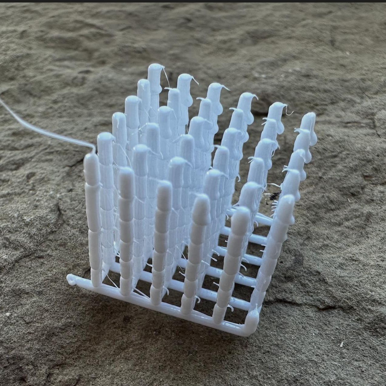
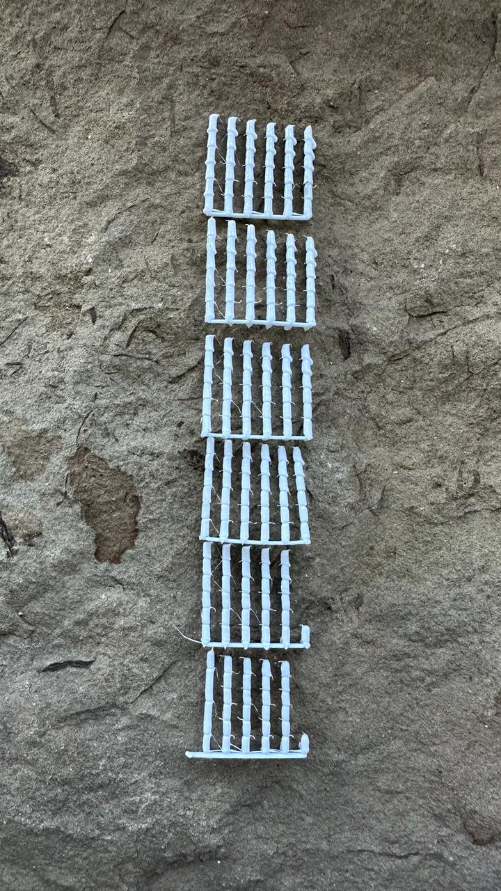
I tried making segmented rods to work around the printhead geometry constraint and print taller rods.
- The printhead slightly touches the rods, so the columns need to be another 0.3 mm shorter.
- Pressing down does not improve anything: it creates asymmetric bulges.
- The best combination is a 0.1 mm thin section, a 0.1 mm³ base drop, and 0% pressing.
- The largest drop produced a nice bamboo-like shape, but even a slightly smaller drop already becomes asymmetric.
Print parameters
Bamboo rods — 2026-09-27 (sketch 2026.09.27 bamboo probe, commit 4d188b1)
Ranges
| Axis | Variable | Values |
|---|---|---|
| X, left to right (X 120.25 … 135.75 in 3.1 mm steps) | height of the thin section of each joint | 0 / 0.1 / 0.2 / 0.3 / 0.4 / 0.5 mm |
| Y, front to back (Y 120.25 … 135.75 in 3.1 mm steps) | base drop for each joint | 0 / 0.1 / 0.2 / 0.3 / 0.4 / 0.5 mm³ |
| Z, joints from bottom to top | base placement | joint 1 — on the grid node; joints 2–6 — below the top of the previous joint by 0 / 25 / 50 / 75 / 100% of that rod's thin-section height |
The front-left corner is marked by a tail on the bed grid.
Print parameters
- Bambu Lab P1S, 0.4 mm nozzle, Textured PEI Plate
- Syntech PETG White, Ø1.75 mm, donor
_donor_3mf/L.gcode.3mf - Temperatures: nozzle at 235 °C throughout the print, including the bed grid (M109 wait before the grid); bed at 70 °C
- Part cooling at 100%
- Field of 6 × 6 rods at 3.1 mm spacing, 15.5 × 15.5 mm between the outer rod axes, centred at X128 Y128; 6 joints per rod, no bridges; rod tops at Z 14.45 … 15.70 mm (calculated)
- Bed grid: 6 lines along X at Z 0.5, each beginning with a 0.2 mm³ drop extruded in place; 6 lines along Y at Z 0.7; 0.8 × 0.5 mm line with 1.2 overfill (0.48 mm³/mm), 10 mm/s; the front-left corner is marked with a tail extending 5 mm left from the front line
- Order: tier by tier — first joints of all 36 rods, then all second joints, and so on. Tier 1 follows a serpentine path from the front-left corner: along X left to right, the next line right to left, with lines proceeding front to back; each following tier traverses the same path in reverse, starting from the rod where the previous tier ended
- Each joint:
- Travel directly at 60 mm/s at the height of the joint just printed (before the first joint, 0.5 mm above the grid).
- Lower to the base.
- Extrude the Y-specific base drop in place at 6 mm³/s; omit it when set to 0.
- Thick section: rise by 2.5 mm minus the thin-section height, extruding 1.1 mm³ per millimetre of rise at 0.5 mm/s (calculated flow 0.55 mm³/s).
- Thin section: rise by its X-specific height, extruding 0.5 mm³ per millimetre of rise at 0.5 mm/s; omit it when set to 0.
- No pause at the top, no retraction, no lift.
- Joint height — thick + thin section = 2.5 mm; the base is not included
- Print time 18 min 51 s, filament 295 mm