G-code
My experiments with 3D printing and generative design
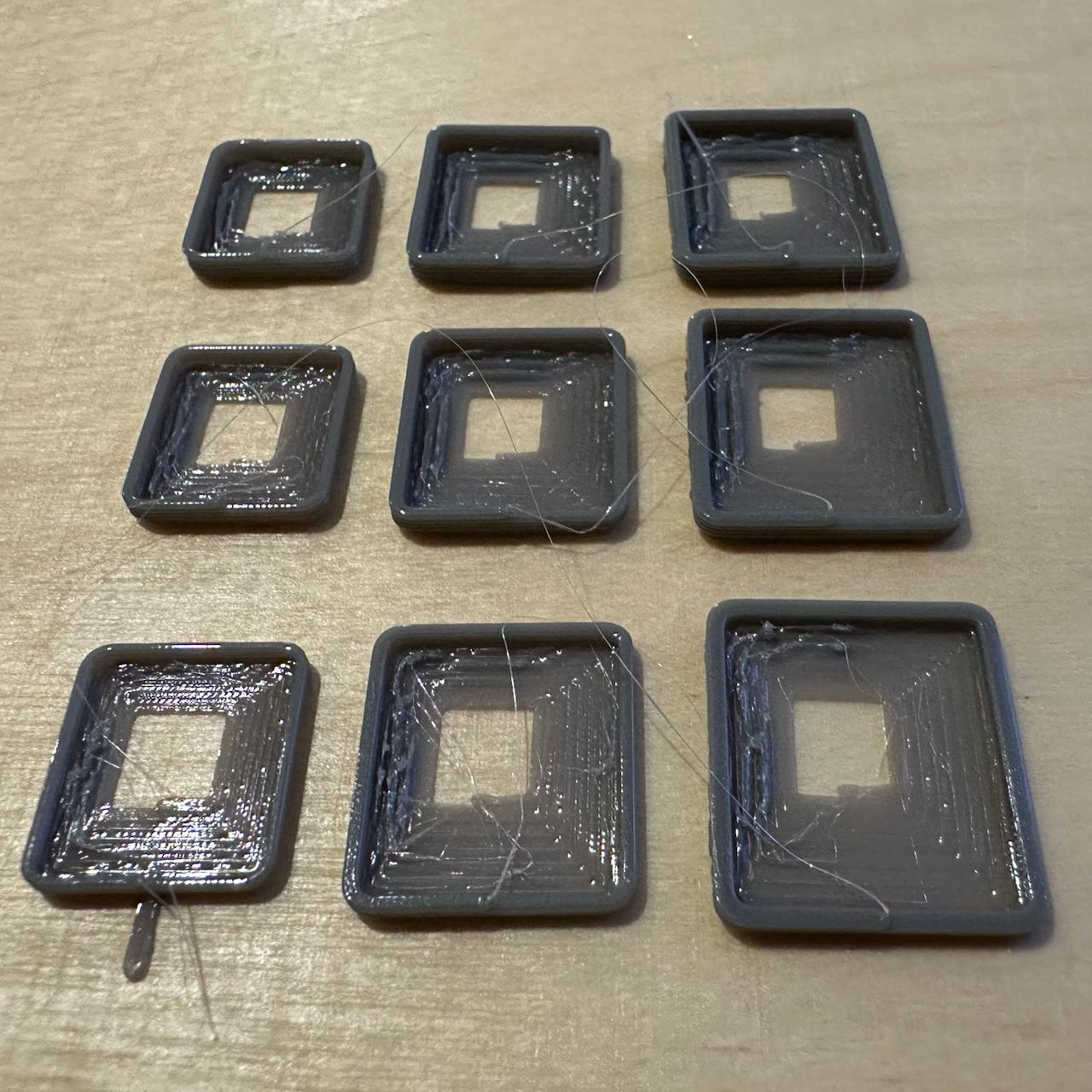
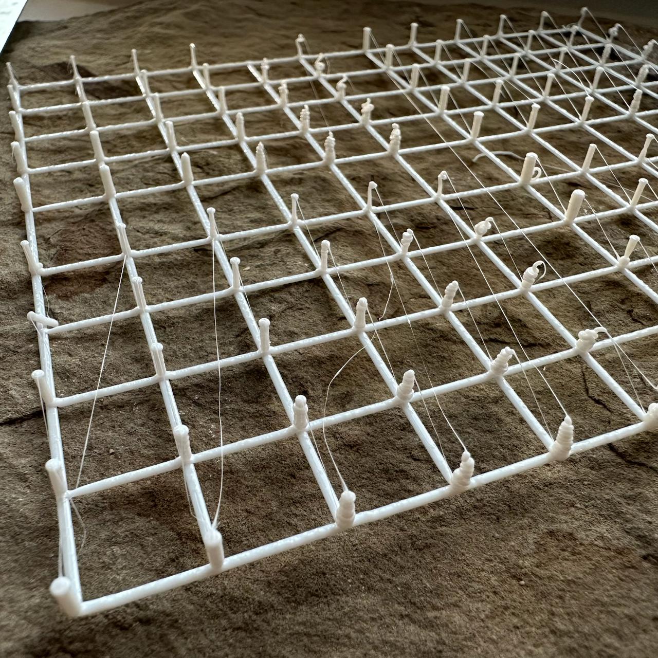
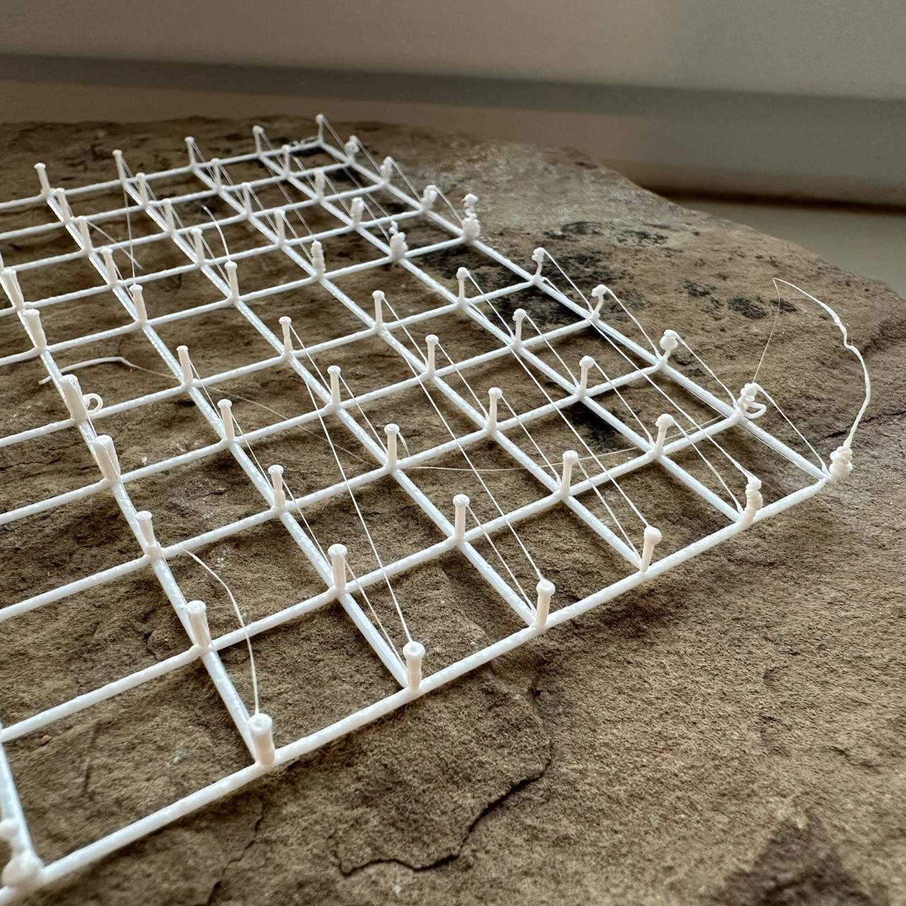
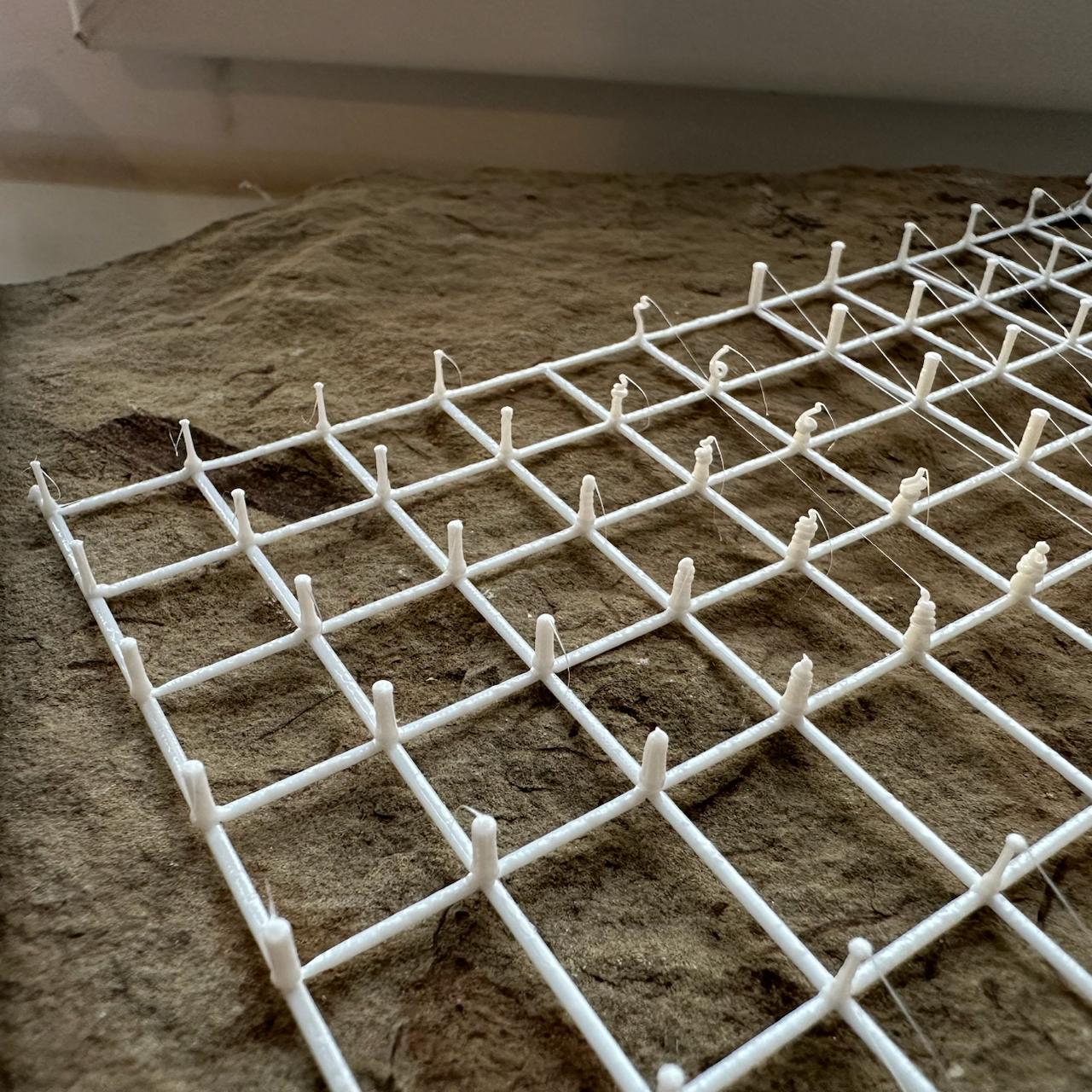
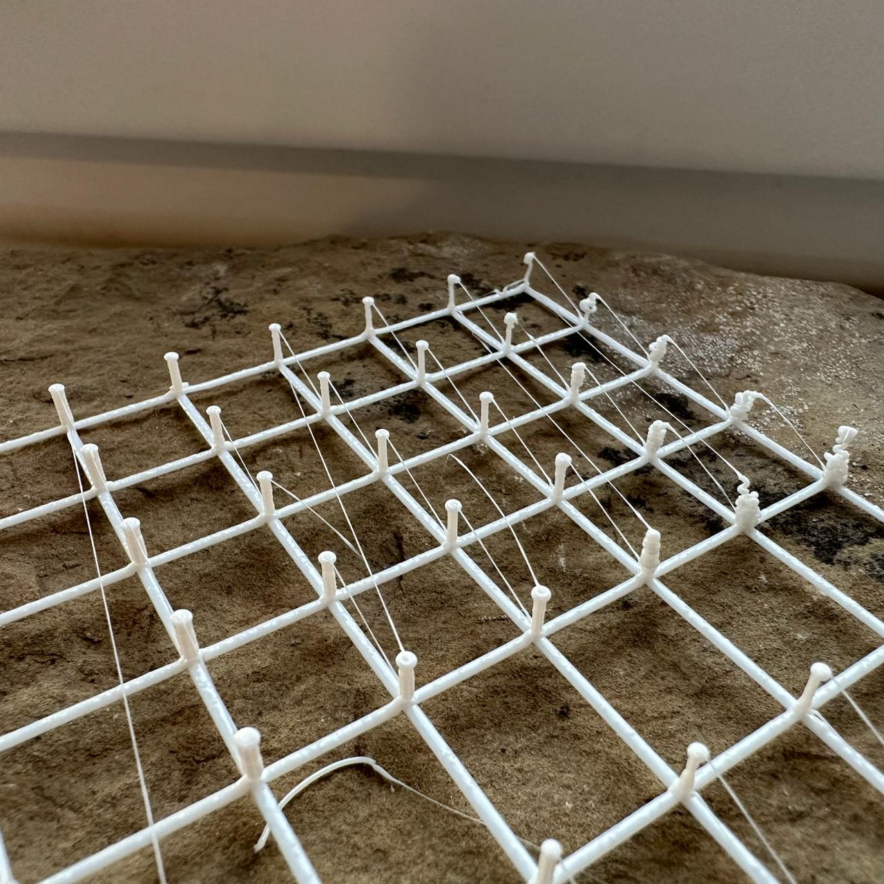
I want to print a Gridfinity box and am tuning the parameters. I varied line width along X, layer height along Y, and used a different floor-coil overlap on each of the four sides of every square. The floor was printed without cooling.
It came out strong even with the sparsest coils. The best result used the thickest layer, the widest line, and the least overlap: it is both fast and visually appealing.
I still need to work out how to close the central hole. I could place four drops in the centre and wind the spiral around them, or simply begin with one large drop.
Interestingly, 0% overlap is sufficient for almost every setting. Only the thinnest line also looks fine at 20%; for the other variants, that is already excessive.
Print parameters
Floor adhesion and initial rise probe — 2026-09-29 (sketch 2026.09.29 spiral floor probe, commit 998669c)
Ranges
| Axis | Variable | Values |
|---|---|---|
| X, left to right | line width | 0.6 / 0.8 / 1.0 mm |
| Y, front to back | layer height (floor and wall) | 0.3 / 0.4 / 0.5 mm |
| Side of the square (the same for all 9 samples) | floor-coil overlap | front 0%, right 20%, back 35%, left 50% |
The field corner is marked with a tail: on the front-left sample, a 5 mm extra segment protrudes from the edge where the floor transitions into the wall.
Print parameters
- Bambu Lab P1S, 0.4 mm nozzle, Textured PEI Plate
- Syntech PETG White, Ø1.75 mm, donor
_donor_3mf/L.gcode.3mf - Temperatures: nozzle 255 °C, bed 70 °C (donor temperatures)
- The sample uses the actual Gridfinity foot profile, size 2 (nominally 41.5 mm, without tolerance), from
2026.09.29 gridfinity foot probe: R0.8 rounding, then a 45° chamfer over 0.8 mm → 1.8 mm vertical section → 45° chamfer over 2.15 mm - Nine samples in a 3 × 3 grid, centres spaced 45 mm apart, field centred at X128 Y128
- Each sample is one continuous seamless spiral, printed at 20 mm/s throughout:
- Floor: from a 3 mm point to the edge (as in the foot), exactly 7 turns; cooling off. Each of the four sides has its own coil pitch and overlap (see ranges), so the final contour is a rectangle rather than a square: at a 1.0 mm line width, the distances from the centre to the edges are front 10.0 / right 8.6 / back 7.55 / left 6.5 mm.
- Wall: without stopping, the same spiral continues upward from the edge for another 5 turns along the actual foot profile (only the beginning of the rise, not the full 4.75 mm height); the side-to-side difference accumulated on the floor is preserved throughout the rise. Cooling is set to 100%.
- Corner rounding grows with the slowest side — the one with the least overlap
- The nozzle centreline is always offset inward from the true outer profile surface by half the line width
- Sample height ranges from 1.8 to 3.0 mm (6 turns at the row's layer height: 1 floor turn + 5 rising turns)
- Print time 4 min 36 s, filament 707 mm
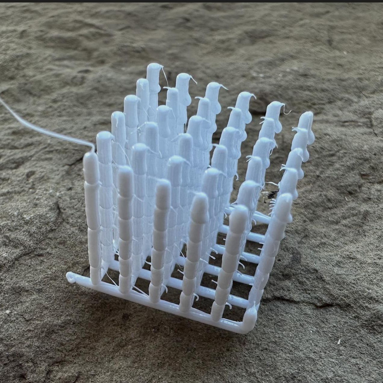
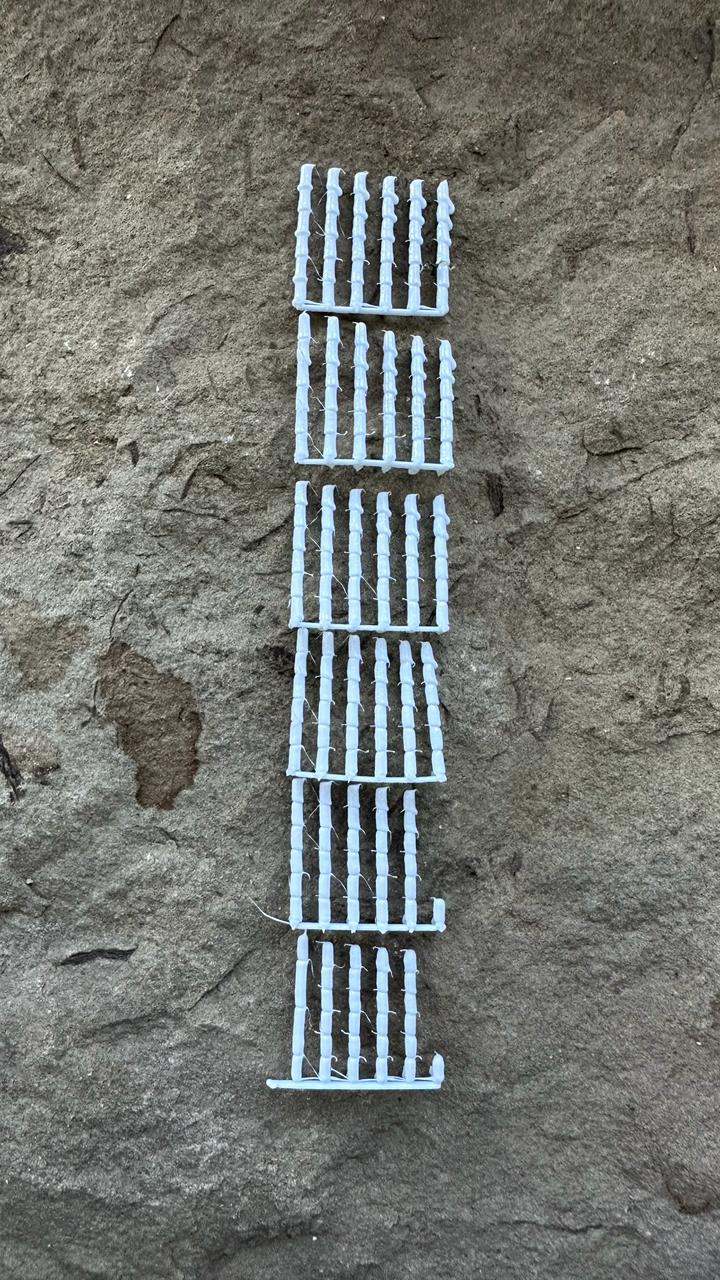
I tried making segmented rods to work around the printhead geometry constraint and print taller rods.
- The printhead slightly touches the rods, so the columns need to be another 0.3 mm shorter.
- Pressing down does not improve anything: it creates asymmetric bulges.
- The best combination is a 0.1 mm thin section, a 0.1 mm³ base drop, and 0% pressing.
- The largest drop produced a nice bamboo-like shape, but even a slightly smaller drop already becomes asymmetric.
Print parameters
Bamboo rods — 2026-09-27 (sketch 2026.09.27 bamboo probe, commit 4d188b1)
Ranges
| Axis | Variable | Values |
|---|---|---|
| X, left to right (X 120.25 … 135.75 in 3.1 mm steps) | height of the thin section of each joint | 0 / 0.1 / 0.2 / 0.3 / 0.4 / 0.5 mm |
| Y, front to back (Y 120.25 … 135.75 in 3.1 mm steps) | base drop for each joint | 0 / 0.1 / 0.2 / 0.3 / 0.4 / 0.5 mm³ |
| Z, joints from bottom to top | base placement | joint 1 — on the grid node; joints 2–6 — below the top of the previous joint by 0 / 25 / 50 / 75 / 100% of that rod's thin-section height |
The front-left corner is marked by a tail on the bed grid.
Print parameters
- Bambu Lab P1S, 0.4 mm nozzle, Textured PEI Plate
- Syntech PETG White, Ø1.75 mm, donor
_donor_3mf/L.gcode.3mf - Temperatures: nozzle at 235 °C throughout the print, including the bed grid (M109 wait before the grid); bed at 70 °C
- Part cooling at 100%
- Field of 6 × 6 rods at 3.1 mm spacing, 15.5 × 15.5 mm between the outer rod axes, centred at X128 Y128; 6 joints per rod, no bridges; rod tops at Z 14.45 … 15.70 mm (calculated)
- Bed grid: 6 lines along X at Z 0.5, each beginning with a 0.2 mm³ drop extruded in place; 6 lines along Y at Z 0.7; 0.8 × 0.5 mm line with 1.2 overfill (0.48 mm³/mm), 10 mm/s; the front-left corner is marked with a tail extending 5 mm left from the front line
- Order: tier by tier — first joints of all 36 rods, then all second joints, and so on. Tier 1 follows a serpentine path from the front-left corner: along X left to right, the next line right to left, with lines proceeding front to back; each following tier traverses the same path in reverse, starting from the rod where the previous tier ended
- Each joint:
- Travel directly at 60 mm/s at the height of the joint just printed (before the first joint, 0.5 mm above the grid).
- Lower to the base.
- Extrude the Y-specific base drop in place at 6 mm³/s; omit it when set to 0.
- Thick section: rise by 2.5 mm minus the thin-section height, extruding 1.1 mm³ per millimetre of rise at 0.5 mm/s (calculated flow 0.55 mm³/s).
- Thin section: rise by its X-specific height, extruding 0.5 mm³ per millimetre of rise at 0.5 mm/s; omit it when set to 0.
- No pause at the top, no retraction, no lift.
- Joint height — thick + thin section = 2.5 mm; the base is not included
- Print time 18 min 51 s, filament 295 mm
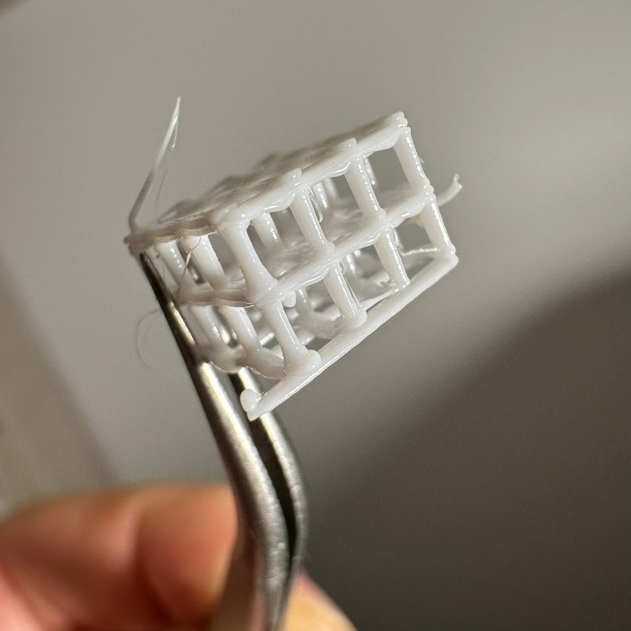
This is perfect. Well, perfect enough for now. I can print a larger one next.
Print parameters
Stem cube, straight travels — 2026-09-26 (sketch 2026.09.26 stem cube straight, commit 8395a88)
- Bambu Lab P1S, 0.4 mm nozzle, Textured PEI Plate
- Syntech PETG White, Ø1.75 mm, donor
_donor_3mf/L.gcode.3mf - Temperatures: nozzle at 235 °C throughout the print, including the bed grid (M109 wait before the grid); bed at 70 °C
- Part cooling at 100%
- Cube of 3 × 3 × 2 cells measuring 3 × 3 × 3 mm each: 4 × 4 nodes at 3 mm spacing, 9 × 9 mm footprint, centred at X128 Y128; top of the final beam at Z 6.7 mm (calculated)
- Bed grid: 4 rows at Z 0.5, 4 columns at Z 0.7, 0.8 × 0.5 mm line with 1.2 overfill (0.48 mm³/mm), 20 mm/s; the front-left corner is marked with a tail extending 5 mm left from the front line
- 2 tiers at 3 mm each: 2.4 mm stem + 0.6 mm beam (4 passes at 0.2 mm increments). Stem tops by tier at Z 3.1 / 6.1
- 16 stems per tier, 32 total; serpentine traversal from the front-left corner: one row left to right, the next right to left, rows front to back
- Each stem:
- Lower to the top of the node with no gap.
- Unretract 0.8 mm and pause for 0.5 s.
- Rise 2.4 mm while extruding 0.5 mm³ per millimetre of rise at 0.5 mm/s (calculated flow 0.25 mm³/s).
- Pause for 1.5 s at the top.
- Retract 0.8 mm, lift 1 mm above the tops, and travel to the next stem at 60 mm/s.
- Beams over the stem tops on each tier, 4 passes at 0.2 mm increments, with the first at stem-top height:
- Layer 1, rows — back to front from the left edge: 0.07 mm³/mm strand, with 0.2 mm³ pads at both ends of the first strand.
- Layer 1, columns — left to right from the front edge: 0.07 mm³/mm strand, with 0.2 mm³ pads at both ends of the first strand.
- Layer 2, rows — front to back from the right edge: 0.14 mm³/mm strand, with 0.2 mm³ pads at both ends of the first strand.
- Layer 2, columns — right to left from the back edge: 0.14 mm³/mm strand, with 0.2 mm³ pads at both ends of the first strand.
- Each beam line consists of two strands offset ±0.175 mm from the node axis (0.35 mm between strands), printed at 15 mm/s: outward along one strand, turn, then back along the other. Pads are extruded in place at 6 mm³/s
- Between beam lines: lift 0.5 mm, travel along the field edge at 60 mm/s, lower; no retraction
- Direct travels: except for the move from the start to the grid, each travel follows X or Y or includes a 0.175 mm offset on the second axis (at a field corner when switching beam passes and from the last beam of a tier to the first stem of the next tier)
- Print time 4 min 32 s, filament 62 mm
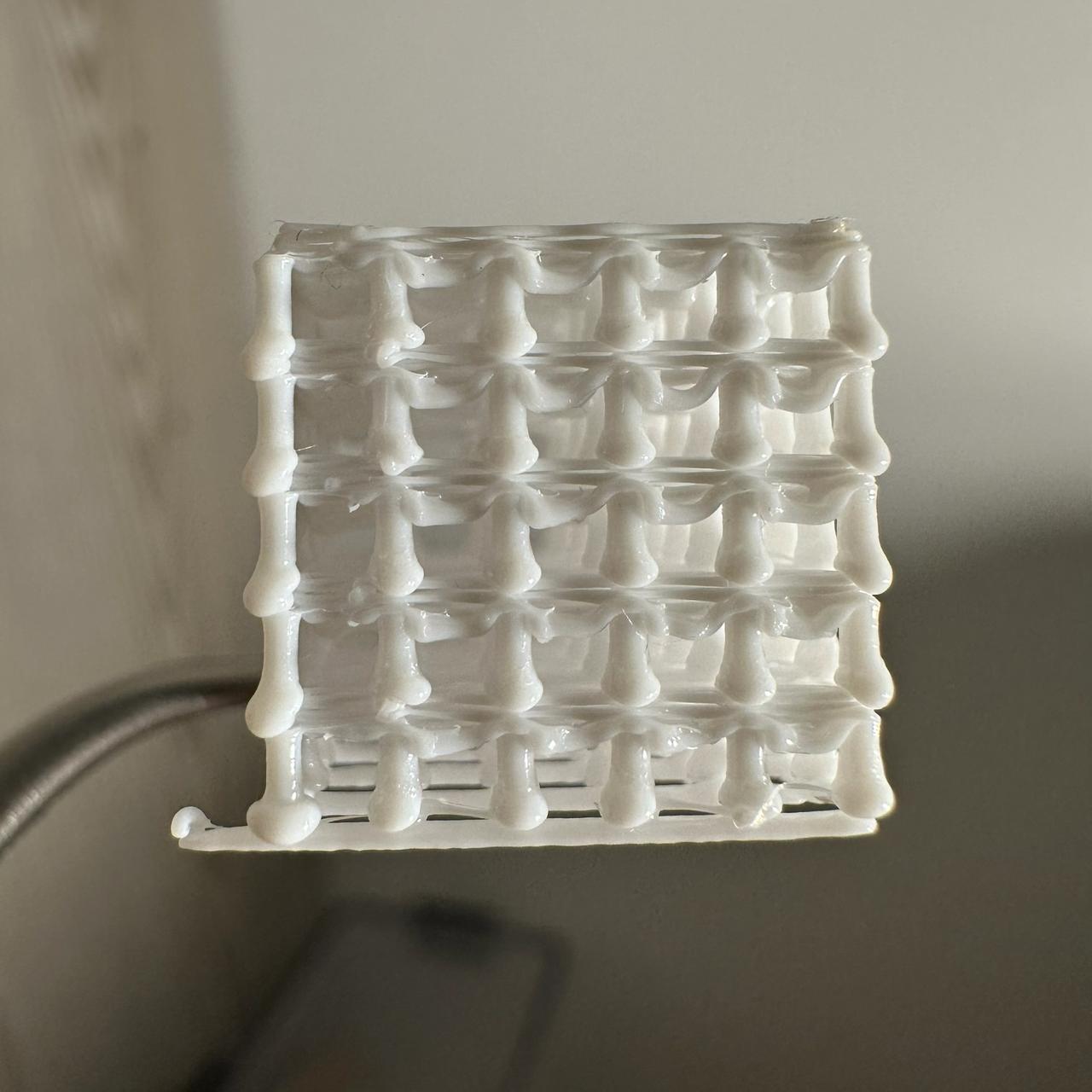
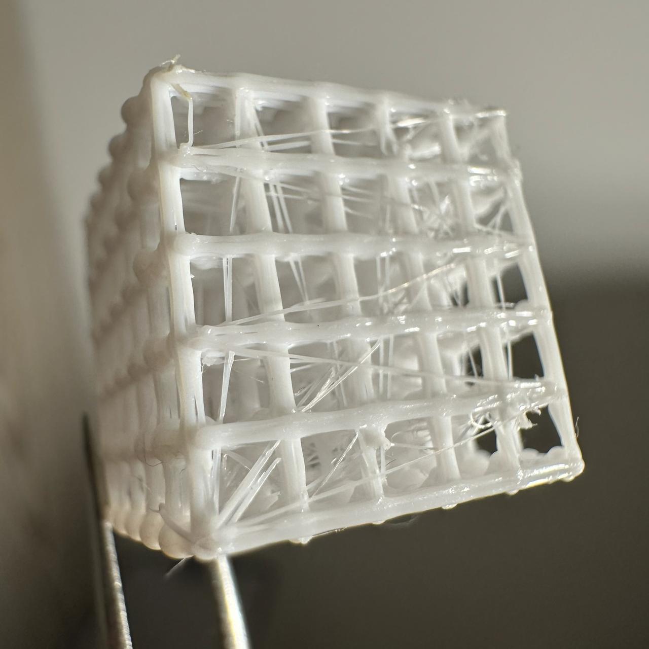
I tried making the bridges thin but printing them in five layers: three along X and two along Y.
A thin line does not land well on another thin line: its end cannot stick, so the nozzle drags it away.
The bridge layers did not fuse. They look fragile, but I could not break the structure by hand.
Viewed from above, there is a lot of webbing caused by diagonal offsets. There are blobs at the bottoms of the columns.
Print parameters
Stem cube, straight travels — 2026-09-26 (sketch 2026.09.26 stem cube straight, commit 8395a88)
- Bambu Lab P1S, 0.4 mm nozzle, Textured PEI Plate
- Syntech PETG White, Ø1.75 mm, donor
_donor_3mf/L.gcode.3mf - Temperatures: nozzle at 235 °C throughout the print, including the bed grid (M109 wait before the grid); bed at 70 °C
- Part cooling at 100%
- Cube of 3 × 3 × 2 cells measuring 3 × 3 × 3 mm each: 4 × 4 nodes at 3 mm spacing, 9 × 9 mm footprint, centred at X128 Y128; top of the final beam at Z 6.7 mm (calculated)
- Bed grid: 4 rows at Z 0.5, 4 columns at Z 0.7, 0.8 × 0.5 mm line with 1.2 overfill (0.48 mm³/mm), 20 mm/s; the front-left corner is marked with a tail extending 5 mm left from the front line
- 2 tiers at 3 mm each: 2.4 mm stem + 0.6 mm beam (4 passes at 0.2 mm increments). Stem tops by tier at Z 3.1 / 6.1
- 16 stems per tier, 32 total; serpentine traversal from the front-left corner: one row left to right, the next right to left, rows front to back
- Each stem:
- Lower to the top of the node with no gap.
- Unretract 0.8 mm and pause for 0.5 s.
- Rise 2.4 mm while extruding 0.5 mm³ per millimetre of rise at 0.5 mm/s (calculated flow 0.25 mm³/s).
- Pause for 1.5 s at the top.
- Retract 0.8 mm, lift 1 mm above the tops, and travel to the next stem at 60 mm/s.
- Beams over the stem tops on each tier, 4 passes at 0.2 mm increments, with the first at stem-top height:
- Layer 1, rows — back to front from the left edge: 0.07 mm³/mm strand, with 0.2 mm³ pads at both ends of the first strand.
- Layer 1, columns — left to right from the front edge: 0.07 mm³/mm strand, with 0.2 mm³ pads at both ends of the first strand.
- Layer 2, rows — front to back from the right edge: 0.14 mm³/mm strand, with 0.2 mm³ pads at both ends of the first strand.
- Layer 2, columns — right to left from the back edge: 0.14 mm³/mm strand, with 0.2 mm³ pads at both ends of the first strand.
- Each beam line consists of two strands offset ±0.175 mm from the node axis (0.35 mm between strands), printed at 15 mm/s: outward along one strand, turn, then back along the other. Pads are extruded in place at 6 mm³/s
- Between beam lines: lift 0.5 mm, travel along the field edge at 60 mm/s, lower; no retraction
- Direct travels: except for the move from the start to the grid, each travel follows X or Y or includes a 0.175 mm offset on the second axis (at a field corner when switching beam passes and from the last beam of a tier to the first stem of the next tier)
- Print time 4 min 32 s, filament 62 mm
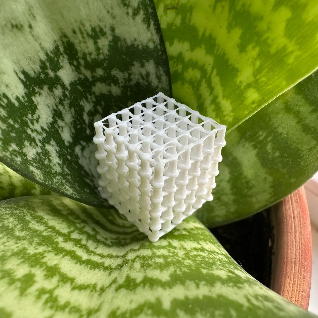
I made the columns too thick; they could be much thinner. All bridges except the top ones — 0.07 mm³/mm — sagged.
The bridges came out very thin compared with the supports. Despite that, the structure is very rigid: I cannot squeeze it with my fingers.
The drops at the bases of the columns are excessive; they inflated into little barrels.
Print parameters
Stem cube — 2026-09-26 (sketch 2026.09.26 stem cube, commit 5f8c95e)
Ranges
- Bridge extrusion: from 0.48 to 0.07 mm³/mm. It stays constant within each tier and changes from tier to tier, bottom to top: 0.48 / 0.35 / 0.25 / 0.15 / 0.07 mm³/mm.
Print parameters
- Bambu Lab P1S, 0.4 mm nozzle, Textured PEI Plate
- Syntech PETG White, Ø1.75 mm, donor
_donor_3mf/L.gcode.3mf - Temperatures: nozzle at 235 °C throughout the print, including the bed-level grid (M109 wait before the grid); bed at 70 °C
- Part cooling at 100%
- Cube of 5 × 5 × 5 cells: 6 × 6 nodes at 3 mm spacing, 15 × 15 mm footprint, centred at X128 Y128; top of the final grid at Z 18.2 mm (calculated)
- Bed grid: 6 rows at Z 0.5, 6 columns at Z 0.7, 0.8 × 0.5 mm line with 1.2 overfill (0.48 mm³/mm), 20 mm/s; the front-left corner is marked with a tail extending 5 mm left from the front line
- 5 tiers at 3.5 mm each: 0.3 mm gap + 3 mm stem + 0.2 mm column lift. Stem tops by tier at Z 4.0 / 7.5 / 11.0 / 14.5 / 18.0
- 36 stems per tier, 180 total; row-wise traversal — each row left to right, rows front to back
- Each stem:
- Lower to the node, stopping 0.3 mm above the top of the node (the grid column beneath it).
- Unretract 0.8 mm and extrude a 2 mm³ base in place at 6 mm³/s.
- Rise 3 mm while extruding 1.4 mm³ per millimetre of rise at 0.5 mm/s (calculated flow 0.7 mm³/s).
- Pause for 1.5 s at the top.
- Retract 0.8 mm, lift 1 mm above the tops, and travel to the next stem at 60 mm/s.
- Grid over the stem tops on each tier:
- Rows at stem-top height, 15 mm/s, using that tier's extrusion; add another 0.5 mm³ in place at every node at 6 mm³/s.
- Columns 0.2 mm above the rows, 15 mm/s, at the same extrusion, with no extra material at the nodes.
- Between lines: lift 0.5 mm, travel at 60 mm/s, lower; no retraction.
- Peak flow 7.2 mm³/s, calculated for bridges at 0.48 mm³/mm × 15 mm/s
- Print time 25 min 34 s, filament 636 mm
At temperatures above 235 °C (245, 255, and 265 °C), the left column (0.2 mm³/mm) came out thicker than the second one (0.5 mm³/mm). Apparently the plastic overheats in the nozzle during the move, or something else happens — who knows.
It is better not to use speeds above 1 mm/s. Rows printed at 2…8 mm/s are unstable at every temperature.
- Retraction wisps still break only at 235 °C.
- The most consistent thicknesses occur at 235 °C. In the three bottom, slowest rows (0.25 / 0.5 / 1 mm/s), the stems measured as follows:
| Extrusion, mm³/mm | Stem Ø, mm ±0.1 mm | Calculated Ø of a solid cylinder with the same volume, mm |
|---|---|---|
| 0.2 | 0.6 | 0.50 |
| 0.5 | 0.8 | 0.80 |
| 0.8 | 1.0 | 1.01 |
| 1.1 | 1.2 | 1.18 |
| 1.4 | 1.4 | 1.34 |
Print parameters
Stem probe with a base — 2026-09-26 (sketch 2026.09.26 stem probe base, commit 69c0b94)
- Printer: Bambu Lab P1S, 0.4 mm nozzle, Textured PEI Plate
- Material: Syntech PETG White, Ø1.75 mm, donor
_donor_3mf/L.gcode.3mf - Temperatures: nozzle at 255 °C for the grid (donor temperature), then 235 / 245 / 255 / 265 °C for the four blocks; bed at 70 °C
- Part cooling: 100%
- Four blocks in a 2 × 2 arrangement, each block 48 × 60 mm, 16 mm gap, field centred at X128 Y128; 235 °C front left, 245 front right, 255 rear left, 265 rear right
- One shared grid for all blocks: rows at Z 0.5, columns at Z 0.7, 0.8 × 0.5 mm line with 1.2 overfill (0.48 mm³/mm), 20 mm/s; the front-left corner is marked by extending the front line 5 mm to the left
- Matrix: extrusion along X is 0.2 / 0.5 / 0.8 / 1.1 / 1.4 mm³ per mm of lift; lift speed along Y (front to back) is 0.25 / 0.5 / 1 / 2 / 4 / 8 mm/s
- Stem spacing: 12 mm; 30 stems per block, 120 total
- Each stem:
- Lower to Z 1.0, leaving a 0.3 mm gap above the grid node.
- Unretract, then extrude a 1 mm³ base in place at 6 mm³/s.
- Rise to Z 5.0: 4 mm with the column's extrusion rate and the row's speed.
- Pause for 1.5 s at the top.
- Travel moves: 0.8 mm retract, rise 1 mm above stem tops, travel at 60 mm/s, lower, then 0.8 mm unretract
- Order: print the entire grid at the donor temperature, then print blocks from coldest to hottest while waiting for each temperature with M109; stems within each block are printed in rows from left to right
- Peak flow: 11.2 mm³/s, calculated for the 1.4 mm³/mm × 8 mm/s cell; the generator reports no warnings
- Print time: 17 min 8 s; filament: 750 mm
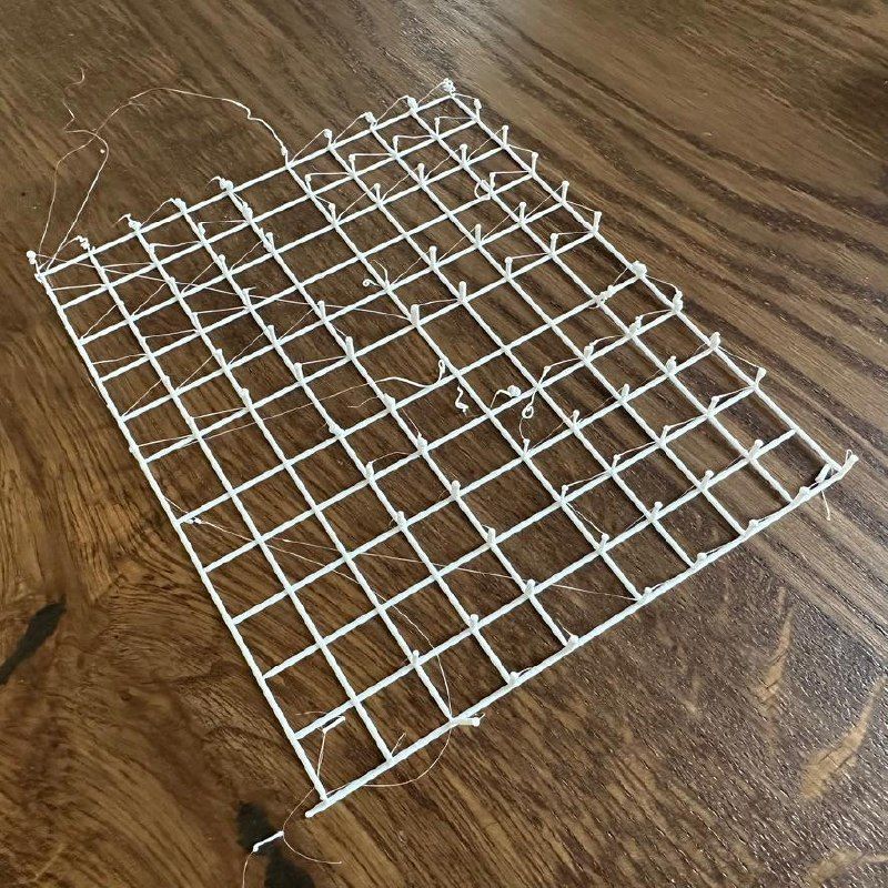
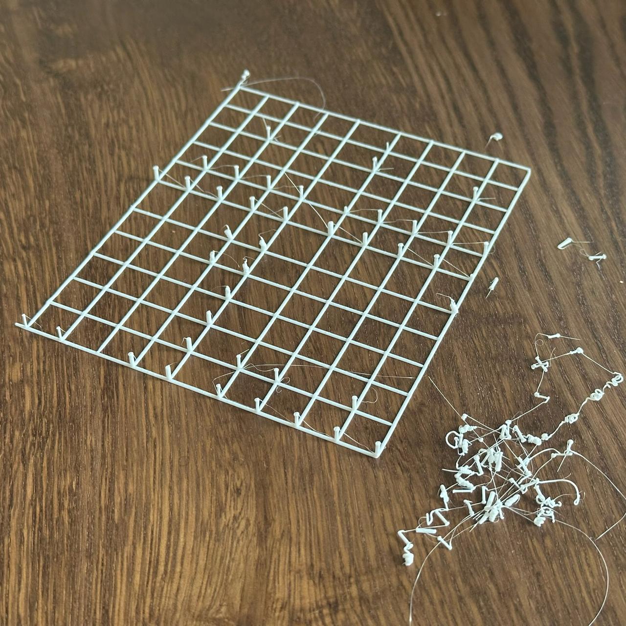
I tried to find suitable parameters for printing a stem. The test piece has four temperature zones, each with a 5 × 6 array of stems.
Within each zone, thickness changes from left to right (thicker on the right), while extrusion speed changes from bottom to top (faster at the top).
In the second photo, I snapped off the stems that came away easily.
For some reason, the thin stems in the first columns become thick, apparently because of the long pause. The pause is there to let the nozzle heat the filament. Some columns have caps on top: this is plastic oozing during the pause.
The stems need to be extruded slowly: only the bottom two rows came out properly. The fine string breaks only at the lowest temperature; at the other temperatures it reaches all the way down to the base.
Print parameters
Stem probe — 2026-09-25 (sketch 2026.09.25 stem probe, commit 8c2a9b4)
- Bambu Lab P1S, 0.4 mm nozzle, Textured PEI Plate
- Syntech PETG White, Ø1.75 mm, donor
_donor_3mf/L.gcode.3mf - Temperatures: nozzle at 255 °C for the base grid (the donor temperature), then 235 / 245 / 255 / 265 °C by block; bed at 70 °C
- Part cooling fan: 100%
- Four blocks in a 2 × 2 arrangement, each 48 × 60 mm, with a 16 mm gap between blocks, centered at X128 Y128; 235 °C front left, 245 °C front right, 255 °C rear left, 265 °C rear right
- One base grid shared by all blocks: rows at Z 0.5, columns at Z 0.7, 0.8 × 0.5 mm line with a 1.2 over-extrusion factor (0.48 mm³/mm), 20 mm/s; the front-left corner is marked by a tail, with the front line extending 5 mm left beyond the field
- Parameter grid: along X, extrusion 0.2 / 0.5 / 0.8 / 1.1 / 1.4 mm³ per mm of upward travel; along Y (front to back), upward speed 0.25 / 0.5 / 1 / 2 / 4 / 8 mm/s
- Stem spacing 12 mm, 30 stems per block, 120 total
- Each stem:
- Descend to Z 0.7, directly to the base-grid node with no gap.
- Unretract 0.8 mm; there is no separate base.
- Rise to Z 5.7, a 5 mm move with the column’s extrusion rate and the row’s speed.
- Pause for 1.5 s at the top.
- Travel moves: retract 0.8 mm, lift 1 mm above the stem tips, travel at 60 mm/s, descend, unretract 0.8 mm
- Order: print the entire base grid at the donor temperature, then print the blocks from coldest to hottest while waiting for each target temperature (M109); within each block, print the stems in a snake pattern, with even rows left to right and odd rows right to left
- Peak flow 11.2 mm³/s, calculated for the 1.4 mm³/mm × 8 mm/s cell
- Print time: 19 min 15 s; filament: 740 mm
Generator — run.py.
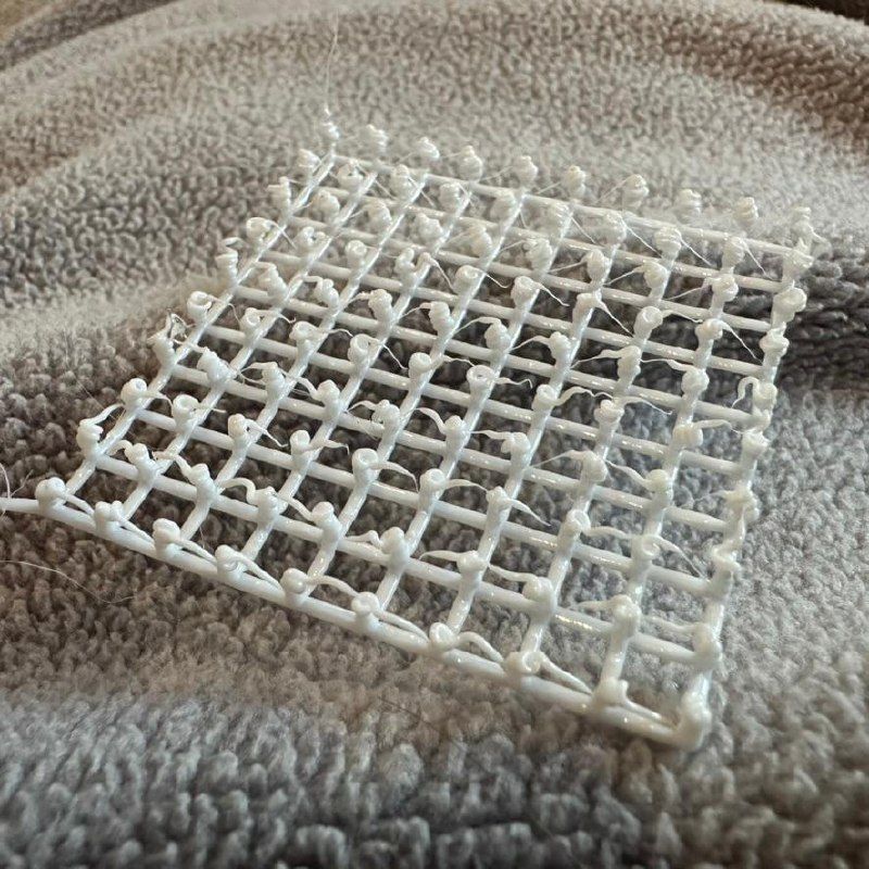
Here I tested different retraction settings, varying the retraction distance and the pause before it.
I misjudged the droplet volume: the filament was extruded either too much or too quickly, so instead of forming a straight line it curled into a knot. With a short pause (the bottom row), the droplets flowed all the way down; with a long two-second pause, they stayed on top of the stems.
I also noticed that the silicone part of the printhead was pressing the neighboring knots down by about 1 mm.
Interestingly, a 1.5-second pause works well and leaves a thin strand. Retraction itself seems to make almost no difference. The collapsed stems may be responsible. I need to learn to draw the stems first and only then retract.
Print parameters
Retraction test — 2026-09-25 (sketch 2026.09.25 retract probe, commit 3e6c6ca)
- Printer, filament, temperatures, and cooling are the same as above
- Field: a 10 × 10 grid of rods at 5 mm spacing (45 × 45 mm), centered on the bed
- Along X, left to right: retraction 0; 0.2; 0.4; …; 1.8 mm
- Along Y, front to back: pause at the top before retraction 0; 0.22; 0.44; …; 2.0 s
- Corner marker at (0, 0), front left: the bottom grid line extends 5 mm to the left beyond the field
- Grid: 0.8 × 0.5 mm lines with 20% over-extrusion (0.48 mm³/mm), 10 mm/s. Rows (along X) at Z 0.5 mm, columns (along Y) at Z 0.7 mm. Each line is printed separately; the nozzle lifts 0.5 mm between lines.
- Rod: rise 5 mm from the top of the grid (Z 0.7) while extruding 0.8 mm³/mm at 5 mm/s (4 mm³ per rod); pause according to its row; retract according to its column at 30 mm/s; lift 1 mm and travel to the next node at 60 mm/s; descend, then unretract by the same distance.
- Path: serpentine by rows
- Print time: 5 min 17 s (excluding start and end); filament: 347 mm
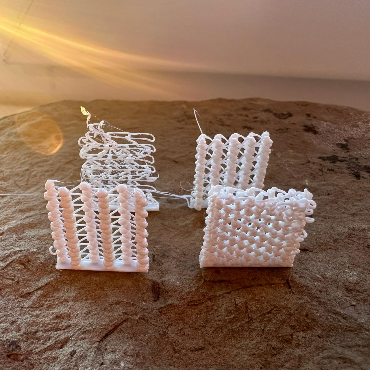
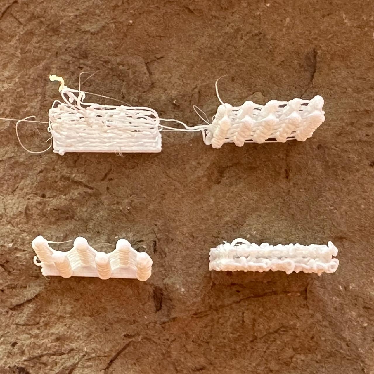
I asked Claude to come up with four walls made of knots and strands on its own.
Print parameters
Four mesh walls — 2026-09-24 (sketch 2026.09.24 mesh walls, commit 8953858)
General:
- Printer, filament, temperatures, and cooling are the same as above
- Four 20 × 4 × 20 mm walls (length × thickness × height) at the corners of a 100 × 100 mm square: A (78, 78), B (178, 78), C (78, 178), D (178, 178)
- The walls are printed one at a time, each in full: A, B, C, D
- Base of each wall: two solid 0.2 mm layers, 0.45 mm lines along the wall, 20 mm/s
- The wall faces run at y = ±1.2 mm from the centerline
- Strand: 0.35 × 0.2 mm (0.07 mm³/mm), 15 mm/s
- Droplets are extruded in place at 6 mm³/s
- Travel between walls: 0.8 mm retraction, lift to 1 mm above everything already printed, travel at 100 mm/s, descend, unretract
- Print time: 8 min 42 s (excluding start and end); filament: 598 mm
A “Truss” (bottom left):
- Six nodes along the wall at 3.6 mm intervals (x = −9…9), alternating between the front and rear faces to form a zigzag in plan view
- A 3 mm³ droplet at each node; node positions stay the same in every row
- Rows alternate direction
- 1.2 mm row height, 16 rows total
B “Running bond” (bottom right):
- 2.5 mm³ droplets on both faces at 4 mm intervals
- In even rows, droplets sit at x = −8, −4, 0, 4, 8; in odd rows, at x = −9, −6, −2, 2, 6, 9
- Each row is a closed loop: front face, crosspiece, rear face, crosspiece
- 1.2 mm row height, 16 rows total
C “Rails and posts” (top left):
- Seven tiers, each 2.86 mm high
- A rail is a continuous line around the perimeter of a tier. The first rests on the base (0.45 × 0.2 mm, 20 mm/s); the others bridge across the tops of the posts (0.45 × 0.3 mm, 8 mm/s). Eight rails total.
- Posts: four on each face per tier; bases spaced 5 mm apart; tops shifted 2.5 mm along the wall
- Each post is printed upward at 0.12 mm³/mm and 4 mm/s, followed by a 0.6 s pause at the top
- Post lean alternates from tier to tier
- Travel between posts: 0.8 mm retraction, 0.5 mm lift
D “Braid with stitches” (top right):
- Five nodes on each face (x = −8…8, 4 mm spacing)
- Even rows: crisscrossed strand, two zigzags between the faces
- Odd rows: ladder pattern — front face, crosspiece, rear face, crosspiece
- A stitch at each node: strand down to 0.2 mm above the row below; 1 mm³ extruded in place; strand back up; 3 mm³ droplet
- 2 mm row height, 10 rows total
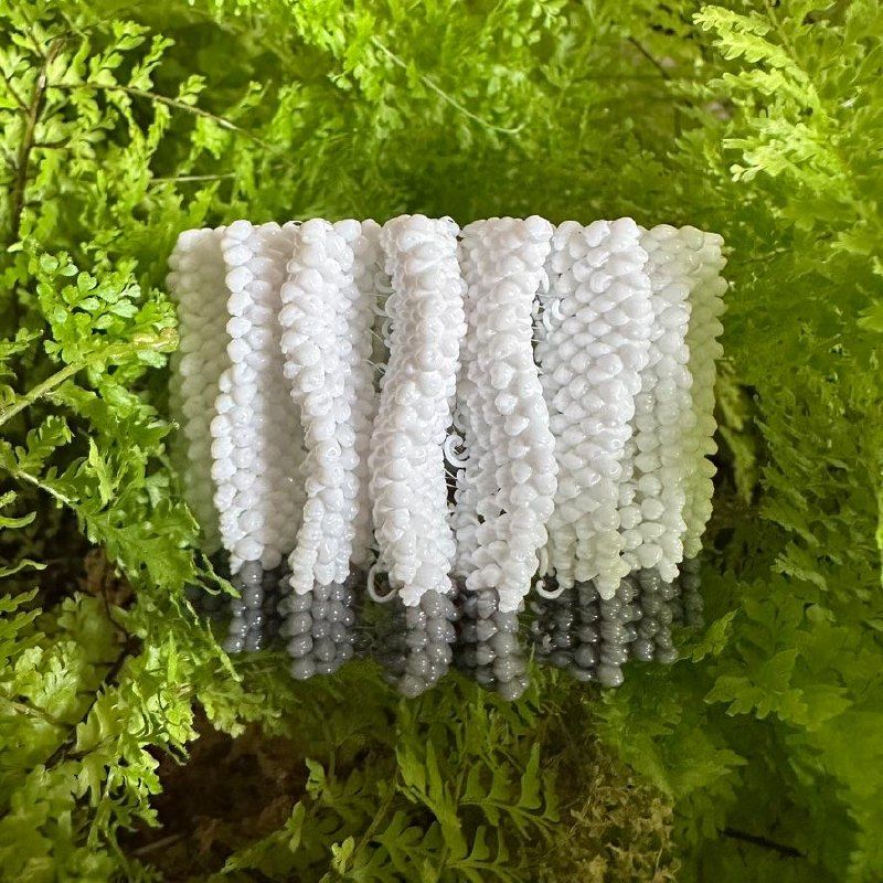
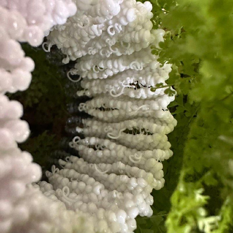
I reduced the layer height, and the result is very strong. The surface looks as if it is made of tiny knots.
Print parameters
Shader lattice on a cylinder, 1 mm layer height — 2026-09-24 (sketch 2026.09.24 shader lattice layer 1mm, commit 0f940c0)
- Bambu Lab P1S, 0.4 mm nozzle, Textured PEI Plate
- Syntech PETG White, Ø1.75 mm
- Temperatures: 255 °C nozzle, 70 °C bed
- Part cooling fan: 100%
- Relief cylinder: radius from 20 to 28 mm (8 mm outward relief), centered at X128 Y128
- Pattern: 10 periods around the circumference, 25.1 mm vertical period
- Base: a continuous line along the lower contour at Z 0.2 mm, 0.5 × 0.2 mm, 20 mm/s
- Layer height: 1 mm. First droplet layer at Z 0.7 mm (0.5 mm above the base), 50 layers total, final layer at Z 49.7 mm
- Droplet spacing along the contour: 4 mm. Each new droplet is placed midway between the droplets of the previous layer.
- Droplet: 2.5 mm³ on the surface, 4 mm³ on the ribs (where the contour runs radially); extruded in place at 6 mm³/s. 5140 droplets total, 5090 of them on the ribs.
- Strand between droplets: 0.35 × 0.2 mm (0.07 mm³/mm), 15 mm/s
- Travel across holes: 0.8 mm retraction, 0.6 mm lift, travel at 60 mm/s, descend, 0.8 mm unretraction. 719 travel moves total.
- Print time: 71 min 19 s (excluding start and end); filament: 8847 mm
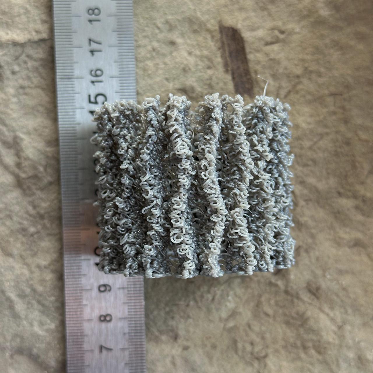
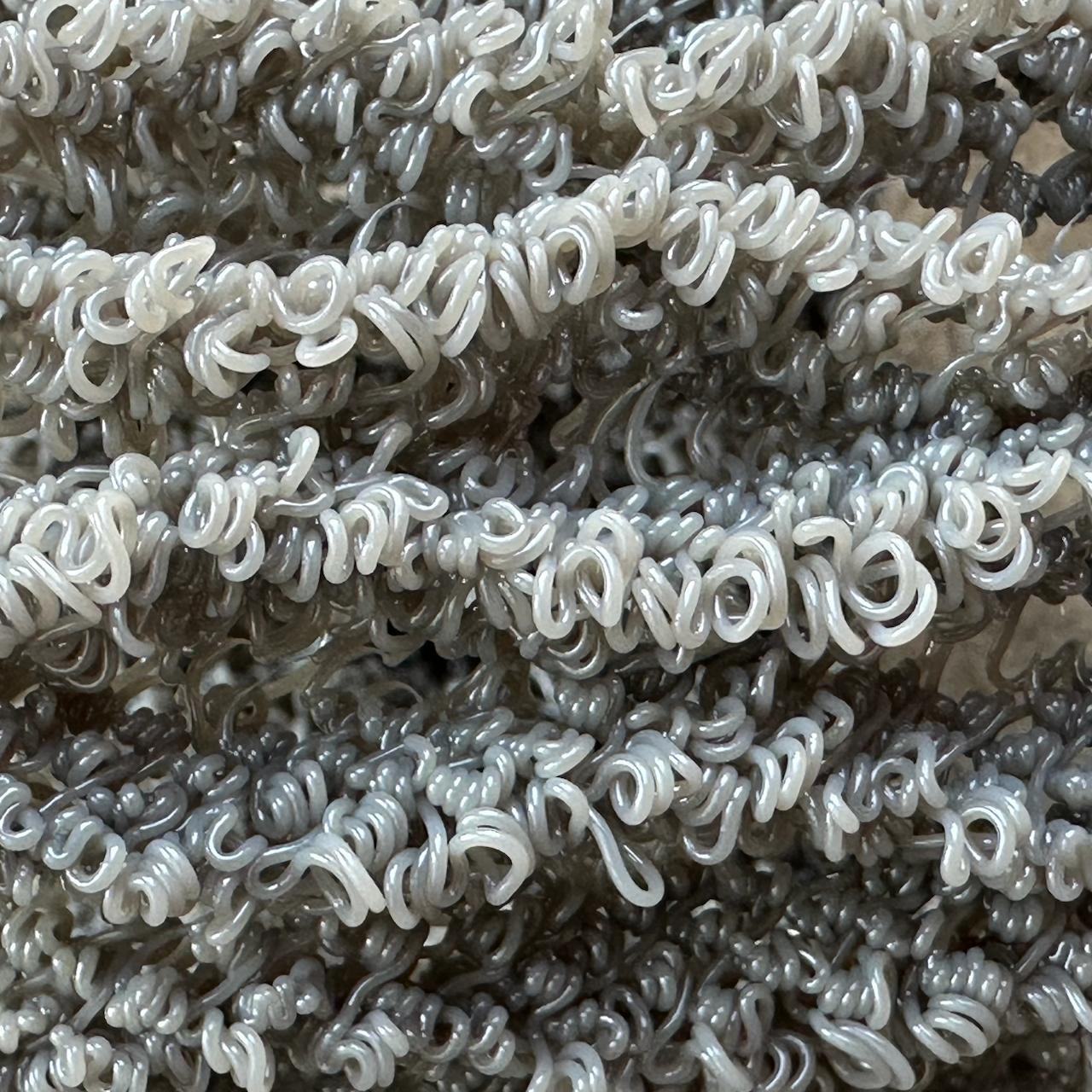
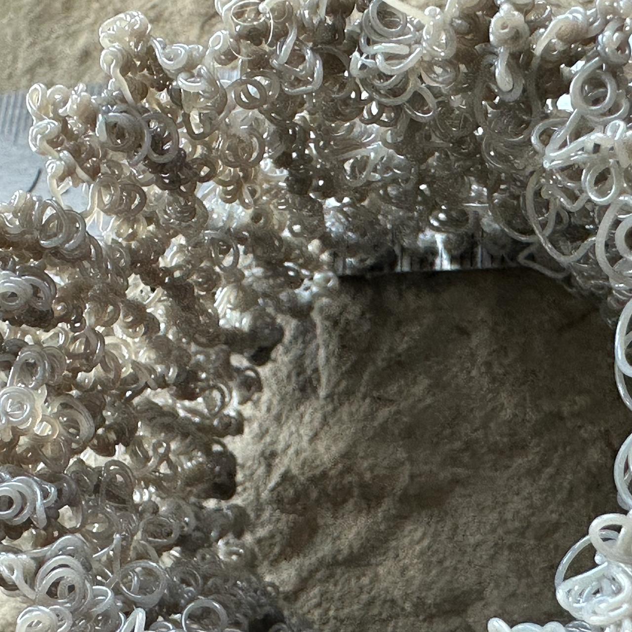
Tested an SDF-defined lattice surface.
For a 4 mm³ droplet, a 2 mm layer is too tall: the layers did not fuse, and the structure falls apart under light pressure. Many droplets fall through the holes in the previous layers. But on the protrusions, where several droplets gather close together, they form a column that keeps the structure from turning into spaghetti.
Print parameters
Shader lattice on a cylinder — 2026-09-24 (sketch 2026.09.24 shader lattice, commit ae2bc4d)
- Bambu Lab P1S, 0.4 mm nozzle, Textured PEI Plate
- Syntech PETG White, Ø1.75 mm
- Temperatures: 255 °C nozzle, 70 °C bed
- Part cooling fan: 100%
- Relief cylinder: radius from 20 to 28 mm (8 mm outward relief), centered at X128 Y128
- Pattern: 10 periods around the circumference, 25.1 mm vertical period
- Base: a continuous line along the lower contour at Z 0.2 mm, 0.5 × 0.2 mm, 20 mm/s
- Layer height: 2 mm; first droplet layer at Z 0.7 mm (0.5 mm above the base); 25 layers total; final layer at Z 48.7 mm
- Droplet spacing along the contour: 4 mm. Each new droplet is placed midway between the droplets of the previous layer.
- Droplet: 2.5 mm³ on the surface, 4 mm³ on the ribs where the contour runs radially. Extruded in place at 6 mm³/s. 2370 droplets total, 2360 of them on the ribs.
- Strand between droplets: 0.35 × 0.2 mm (0.07 mm³/mm), 15 mm/s
- Travel across holes: 0.8 mm retraction, 0.6 mm lift, travel at 60 mm/s, descend, 0.8 mm unretraction. 369 travel moves total.
- Print time: 33 min 31 s; filament: 4107 mm
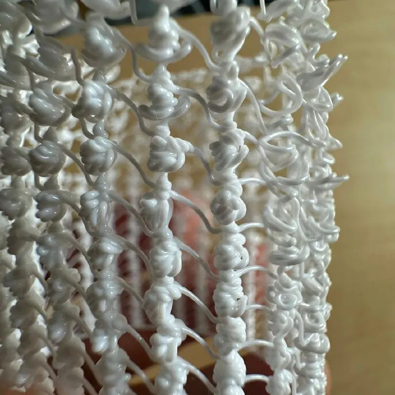
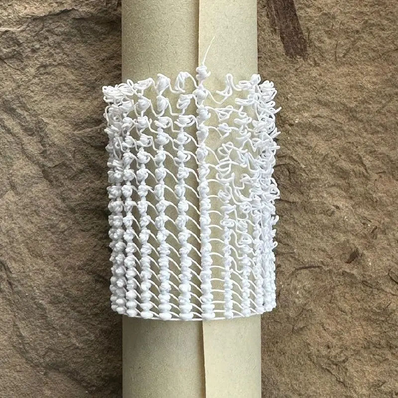
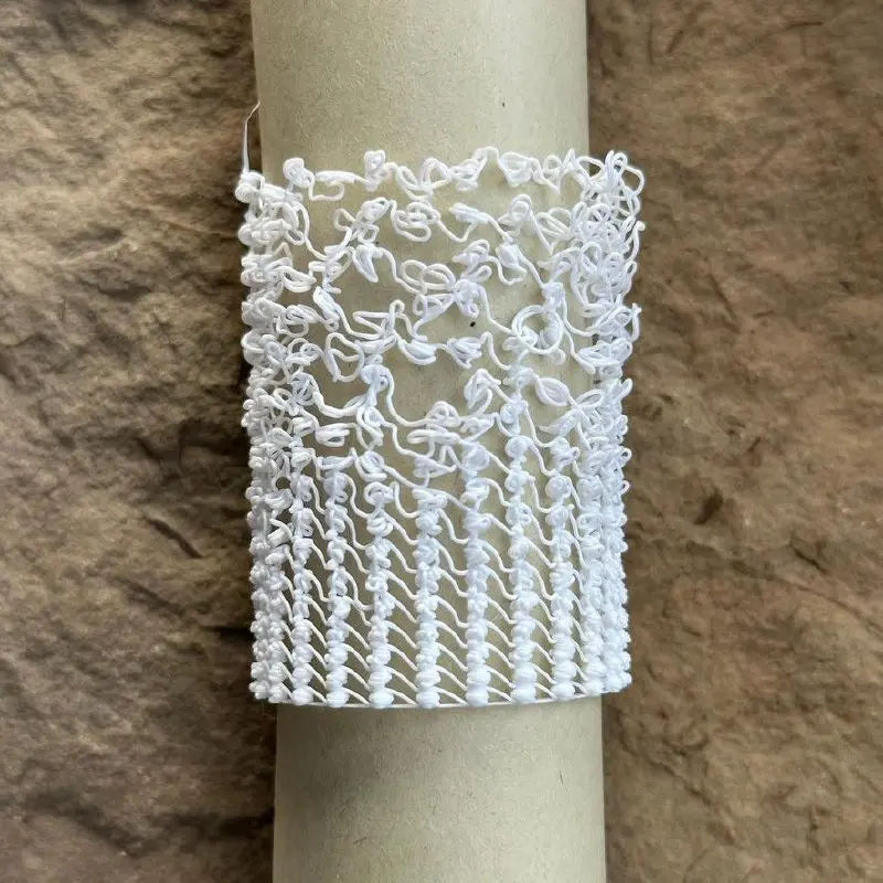
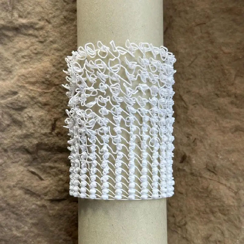
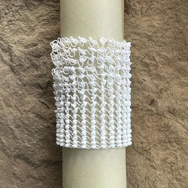
Droplet spiral stitch
Another test print of a spiral with changing parameters. The new algorithm:
- The nozzle travels to the new knot with normal extrusion.
- It descends with extrusion toward the previous turn, stopping 0.2 mm short.
- It extrudes 1 mm³ in place.
- It rises back to the turn height with normal extrusion.
- It extrudes the droplet.
Pitch: 2…5 mm. Droplet volume: 4…8 mm³.
Some interesting observations:
- I realized too late that on the taller turns the toolhead should hit neighboring droplets. It never did. Possibly the droplets ended up below their intended height because the openwork structure sagged.
- At low droplet volumes the turns fell apart, but not completely: they still fused a little.
- I thought the strand in the previous spiral broke because of the long pause before travel. But perhaps it happened because the nozzle descended without extrusion and pulled on the short horizontal strand.
Experiment data
Droplet spiral stitch — 2026-09-23 (sketch 2026.09.23 drip spiral stitch, commit 67fa49a)
Ranges
- Droplet volume: 4 to 8 mm³. It follows a sawtooth over every revolution: the first droplet (0°) is 4 mm³ and the last one (345.6°) is 8 mm³, increasing by 1/6 mm³ ≈ 0.167 mm³ per droplet. Formula:
V(i) = 4 + 4·i/24, i = 0…24. - Pitch: 2 to 5 mm. It stays constant within each revolution and increases stepwise by 0.1875 mm on every new revolution. Formula:
h(n) = 2 + 3·(n−1)/16, n = 1…17. Values by turn, mm: 1 — 2.00 · 2 — 2.19 · 3 — 2.38 · 4 — 2.56 · 5 — 2.75 · 6 — 2.94 · 7 — 3.13 · 8 — 3.31 · 9 — 3.50 · 10 — 3.69 · 11 — 3.88 · 12 — 4.06 · 13 — 4.25 · 14 — 4.44 · 15 — 4.63 · 16 — 4.81 · 17 — 5.00.
Print parameters
- Bambu Lab P1S, 0.4 mm nozzle, Textured PEI Plate
- Syntech PETG White, Ø1.75 mm
- Temperatures: 255 °C nozzle, 70 °C bed
- Part cooling fan: 100%
- Cylinder Ø40 mm, centered at X128 Y128
- Base: 3 spiral turns at Z 0.2 mm (radii 18.65…20 mm), 0.5 × 0.2 mm line, 20 mm/s
- 25 droplets per revolution, 14.4° step, 5.03 mm arc distance between droplets
- Flat turns: every droplet of a revolution is at the same height; the lift to the next turn happens at the end of the revolution
- Each droplet:
- A 0.35 × 0.2 mm strand (0.07 mm³/mm) at 15 mm/s to the next droplet, at turn height.
- Descend with the same strand at 15 mm/s to the top of the droplet on the previous turn + 0.2 mm.
- Extrude 1 mm³ in place (6 mm³/s).
- Rise with the same strand at 15 mm/s back to turn height along the same vertical line.
- Extrude droplet V(i) in place at 6 mm³/s (4 mm³ in 0.67 s, 8 mm³ in 1.33 s).
- 17 turns, total height 59.7 mm
- Print time: 14 min 7 s; filament: 1396 mm
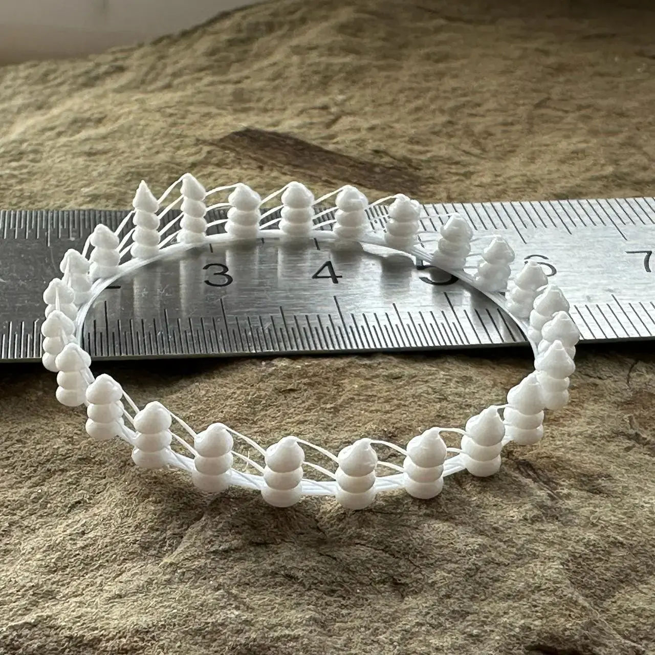
Droplet spiral with a nozzle dip: before each droplet, the nozzle drops down to the droplet on the previous turn.
I printed the first 3 turns. Every droplet came out smooth, no knots. When the nozzle moves sideways after a droplet, the strand at the droplet thins almost to breaking.
Experiment data
| Droplet, mm³ | Pitch, mm | Result |
|---|---|---|
| 1 + 4.00 … 1 + 8.00 | 1.50 / 1.56 / 1.62 (turns 1–3) | smooth droplets; the strand thins almost to breaking at the droplet |
Print parameters
- Bambu Lab P1S, 0.4 mm nozzle, Textured PEI Plate
- Syntech PETG White, Ø1.75 mm
- Temperatures: 255 °C nozzle, 70 °C bed
- Part cooling fan: 100%
- Cylinder Ø40 mm, centered at X128 Y128
- Base: 3 spiral turns at Z 0.2 mm (radii 18.65…20 mm), 0.5 × 0.2 mm line, 20 mm/s
- 25 droplets per revolution, 14.4° step, 5.03 mm arc distance between droplets
- Flat turns: all droplets of a revolution at one height, the lift to the next turn happens at the end of the revolution
- Pitch increases stepwise on every revolution: from 1.5 mm (turn 1) to 3.0 mm (turn 27),
h(n) = 1.5 + 1.5·(n−1)/26 - Droplet volume follows a sawtooth over every revolution, from 4 to 8 mm³:
V(i) = 4 + 4·i/24, i = 0…24 - Each droplet:
- 0.35 × 0.2 mm strand at 15 mm/s to the next droplet, at turn height;
- travel down without extrusion at 10 mm/s to the top of the droplet on the previous turn + 0.2 mm;
- 1 mm³ extruded in place (6 mm³/s);
- rise back to turn height while extruding V(i) at 6 mm³/s (≈1–3 mm/s);
- 1 s pause.
- Full file: 27 turns, 61.0 mm tall, 30 min 49 s, 2078 mm of filament; the first 3 turns were printed
Observations
- Dipping the nozzle to the previous turn did not produce knots: at 1.5–1.62 mm pitch and 5–9 mm³ droplets, every droplet is smooth.
- The weak spot is where the strand leaves the droplet. A possible cause: during the 1 s pause under full cooling the top of the droplet cools down, so the thin strand (0.07 mm³/mm) barely fuses to it and gets stretched instead.
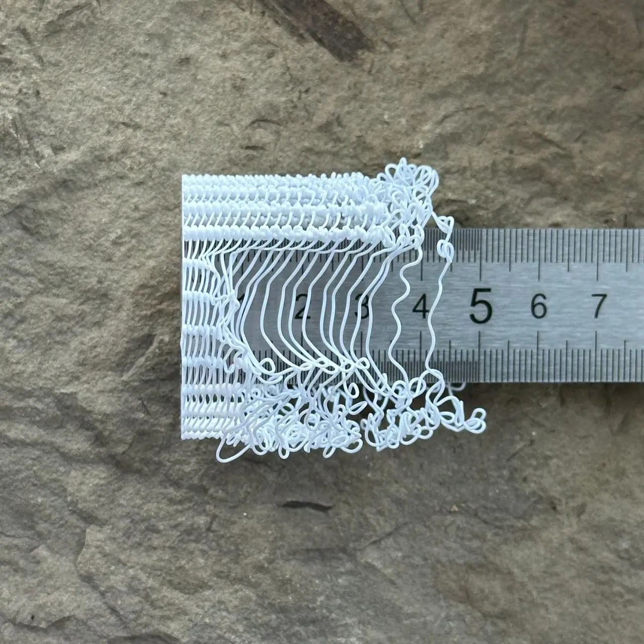
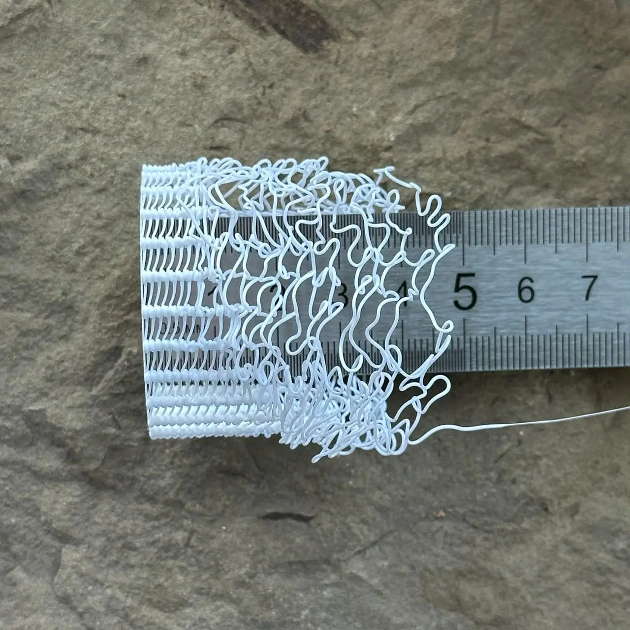
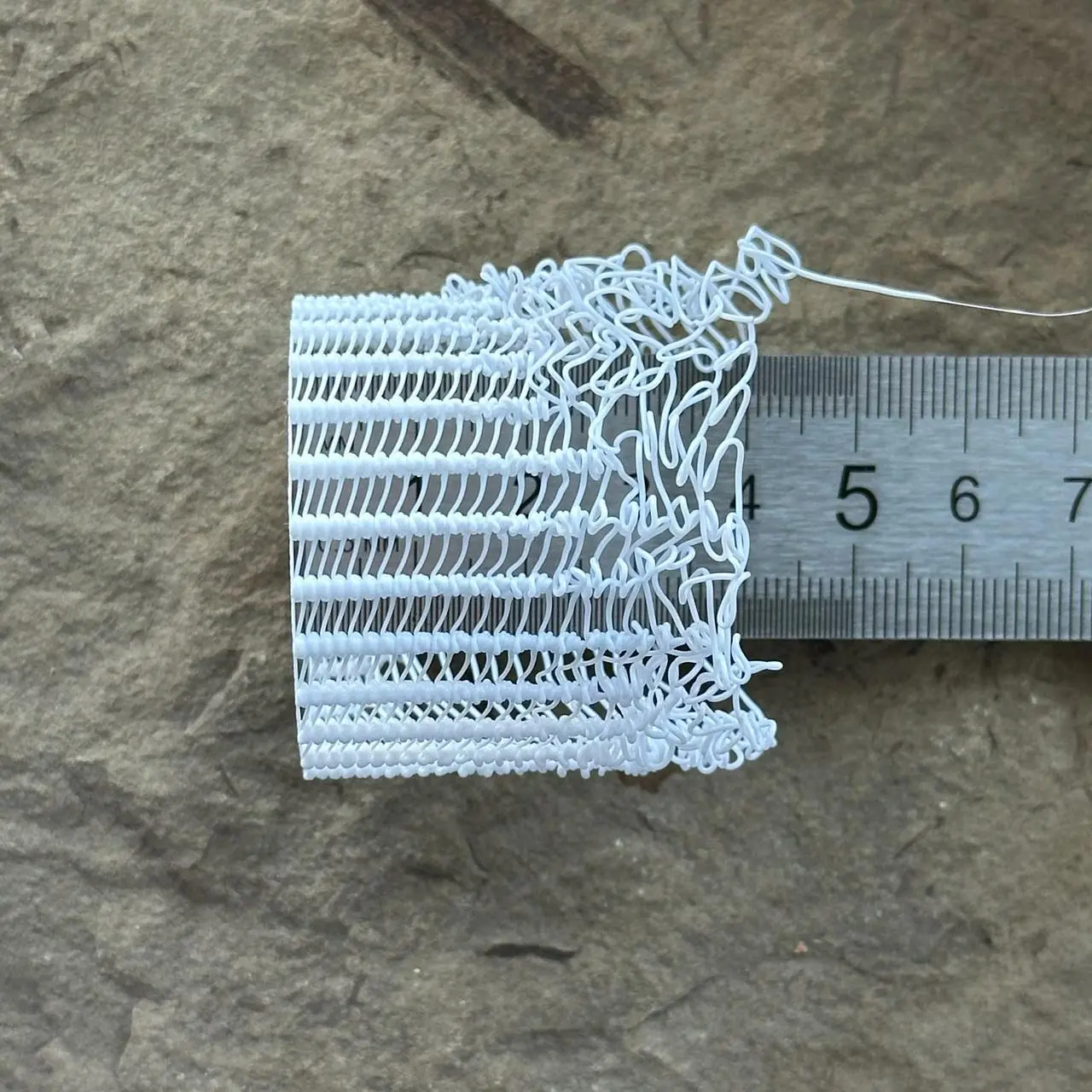
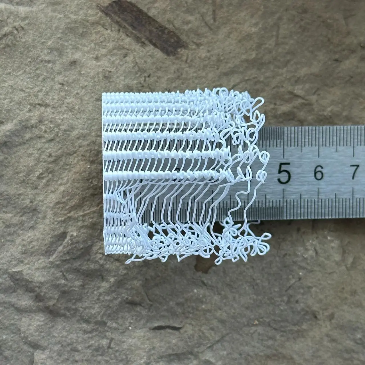
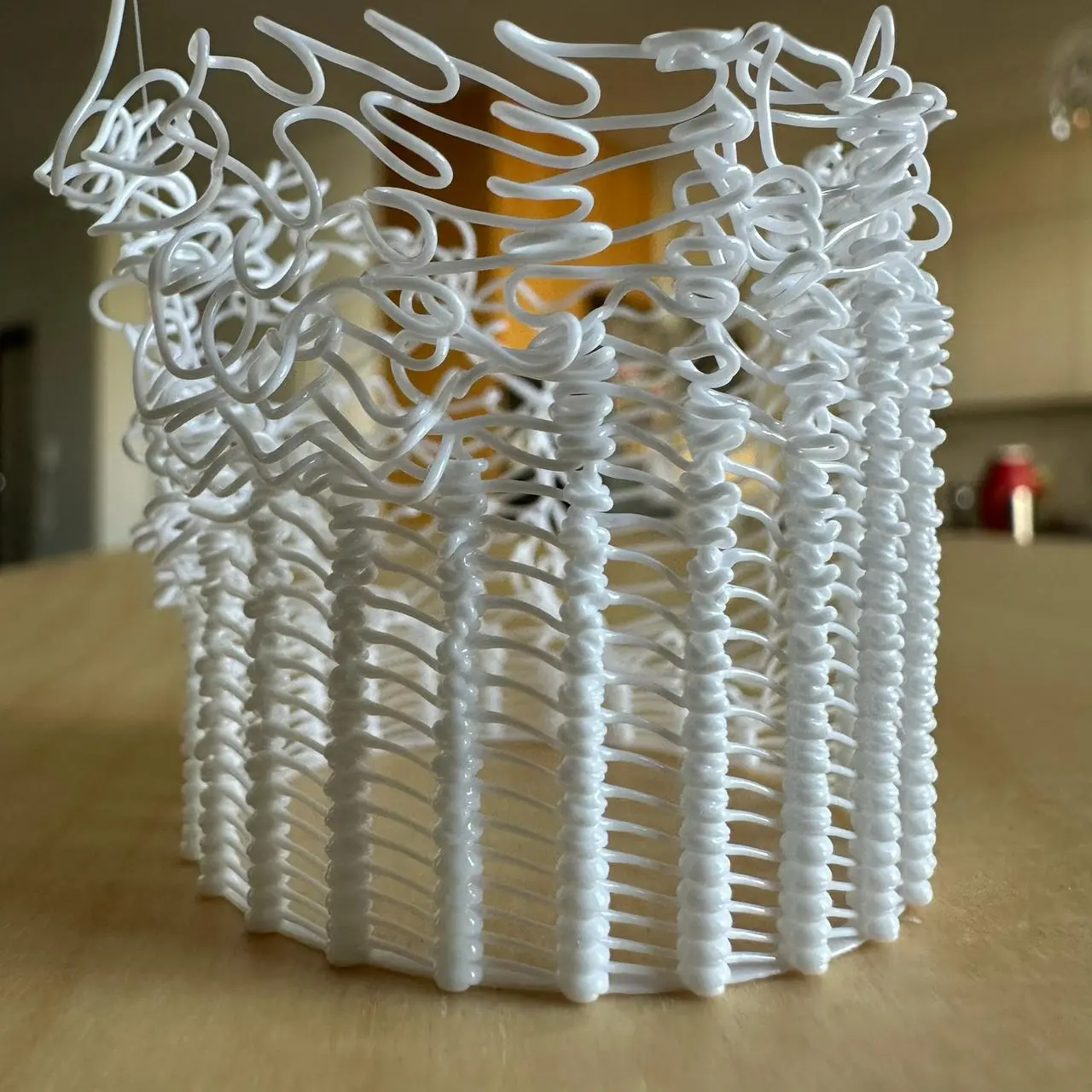
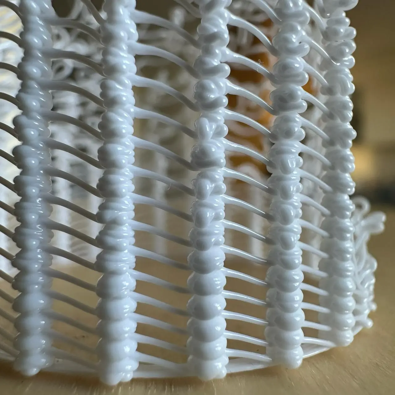
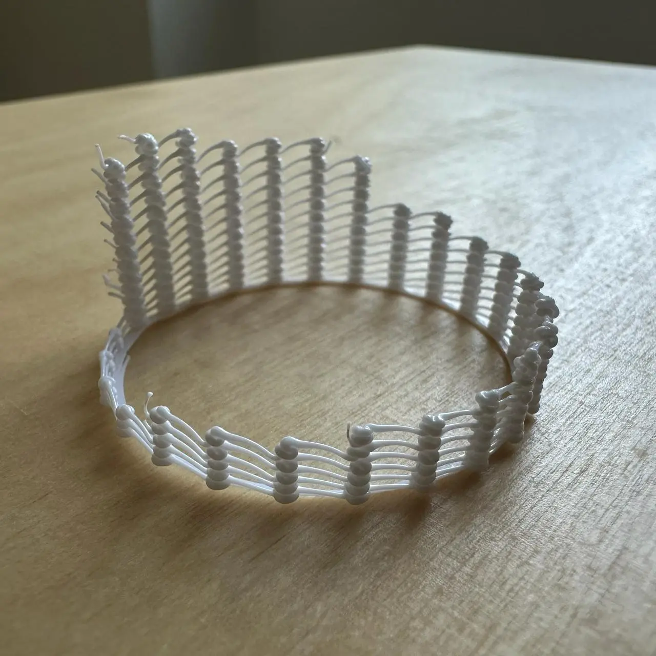
Droplet spiral.
An idea for the next iteration: touch the previous turn with the nozzle before extruding each droplet, so that the layers fuse more reliably.
Experiment data
Pitch is how far each turn sits above the previous one, i.e. the height from which a droplet is extruded onto the turn below.
| Droplet, mm³ | Knots begin at pitch, mm | Maximum pitch, mm |
|---|---|---|
| 1.00 | — (no knots) | 1.14 |
| 1.50 | 1.14 | 1.14 |
| 2.00 | 1.21 | 1.35 |
| 2.50 | 1.21 | 1.41 |
| 3.13 | 1.41 | 1.48 |
| 3.63 | 1.41 | 1.76 |
| 4.00 | 1.55 | 1.76 |
Print parameters
- Bambu Lab P1S, 0.4 mm nozzle, Textured PEI Plate
- Syntech PETG White, Ø1.75 mm
- Temperatures: 255 °C nozzle, 70 °C bed
- Part cooling fan: 100%
- Cylinder Ø40 mm, centered at X128 Y128
- Base: 3 spiral turns at Z 0.2 mm (radii 18.65…20 mm), 0.5 × 0.2 mm line, 20 mm/s
- First wall turn at Z 0.7 mm, or 0.5 mm above the base
- 25 droplets per revolution, 14.4° step, 5.03 mm arc distance between droplets
- Connecting strand: 0.35 × 0.2 mm, 15 mm/s
- Pitch remains constant within each revolution and increases stepwise on every new revolution: from 1.0 mm (turn 1) to 3.0 mm (turn 30),
h(n) = 1 + 2·(n−1)/29 - Droplet volume follows a sawtooth over every revolution, growing from 1 to 4 mm³:
V(i) = 1 + 3·i/24, i = 0…24 - Each droplet is extruded in place at 6 mm³/s: 1 mm³ in 0.17 s, 4 mm³ in 0.67 s
- 30 revolutions, total height 60.7 mm
- Print time: 9 min 44 s; filament: 904 mm
Observations
- The larger the droplet, the higher the wall remains intact and the later smooth droplets turn into knots.
- In every sector, the wall breaks within 0–5 revolutions after the knots begin to appear.
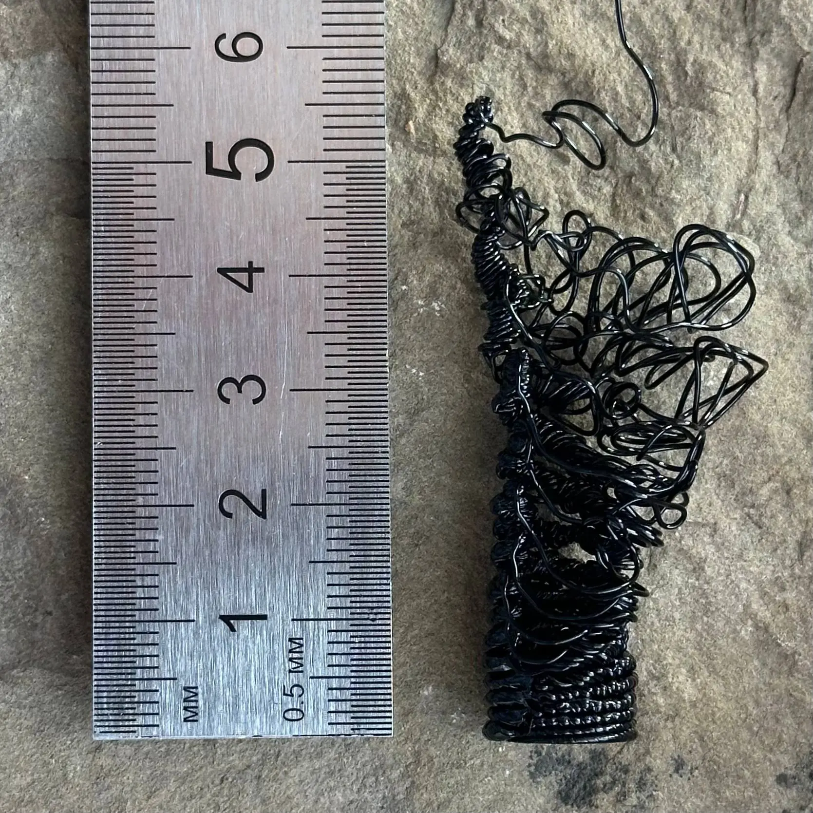
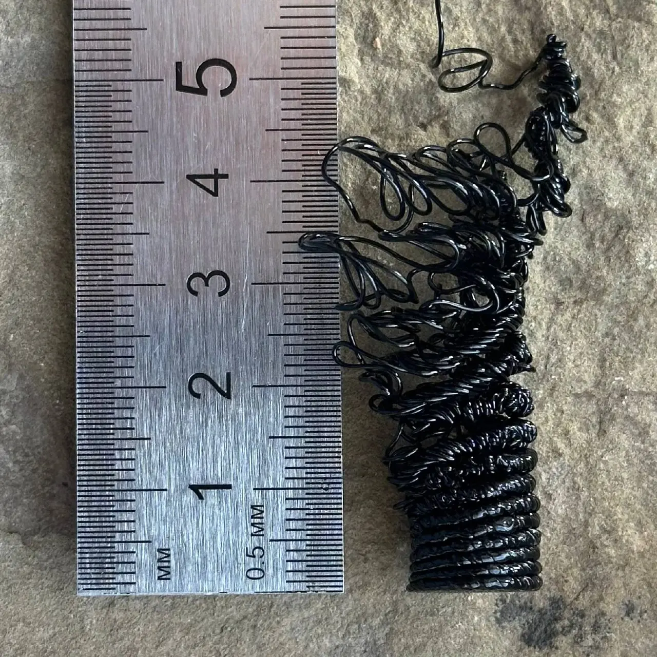
A droplet wall: droplet volume increases within each revolution, while the spiral pitch gradually grows from bottom to top. In the upper section, the connecting strand could no longer hold the droplets together, and the structure unraveled into loops.
Technical parameters
Geometry
- Cylinder radius: 5 mm (10 mm diameter)
- Total print height: 60.2 mm (0.2 mm base + 60 mm droplet wall)
- Angular step between droplets: 10°, or 36 droplets per revolution
- Horizontal arc distance between adjacent droplets at a 5 mm radius: 0.873 mm
Spiral pitch
Vertical rise per revolution:
- from 1 mm at the bottom to 10 mm at the top
- one smooth linear transition over the full height
Droplet volume
- From 0.01 mm³ to 5 mm³
- Angular sawtooth: linear growth over the full revolution (0→360°), followed by an abrupt reset to the minimum at the start of the next revolution
- Each droplet is extruded in place without nozzle movement: the nozzle travels to the point and extrudes while stationary
Droplet extrusion speed
- Constant: 50% of the donor filament profile's maximum volumetric flow. For PETG on the P1S this is 12 mm³/s, so the experiment uses 6 mm³/s regardless of droplet size
- Converted to filament feed for 1.75 mm filament: 2.5 mm/s; in G-code this is
F150
Connecting strand
It holds the droplets together around the circumference; without it, the structure cannot stand.
- Width: 0.35 mm
- Cross-section height: 0.2 mm
- Volume per millimeter of travel: 0.07 mm³/mm
- Travel speed: 15 mm/s
- Independent of spiral pitch, so its thickness remains constant
Base
- Solid disk for bed adhesion
- Spiral from center to edge, with a 0.5 mm line width and 0.2 mm height
- The number of turns is chosen for approximately 10% overlap, leaving no gaps
Donor: L-profile by Justagwas
Material: PETG
Printer: Bambu Lab P1S
Nozzle: 0.4 mm
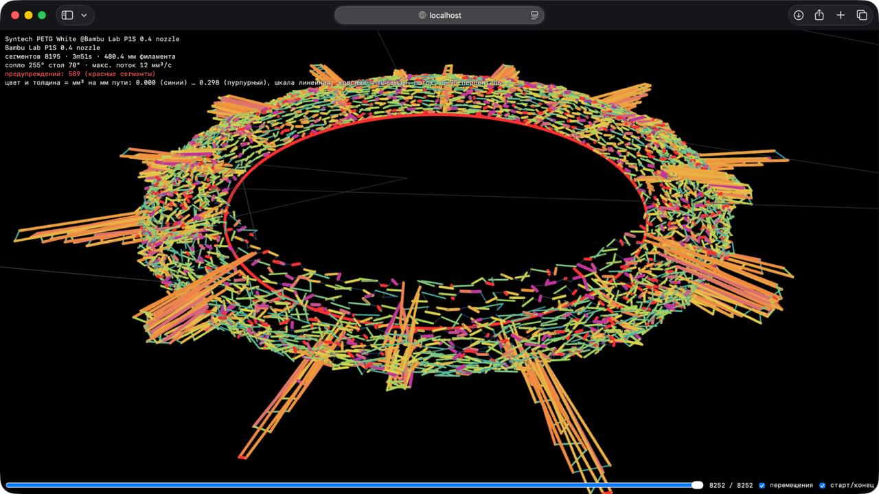
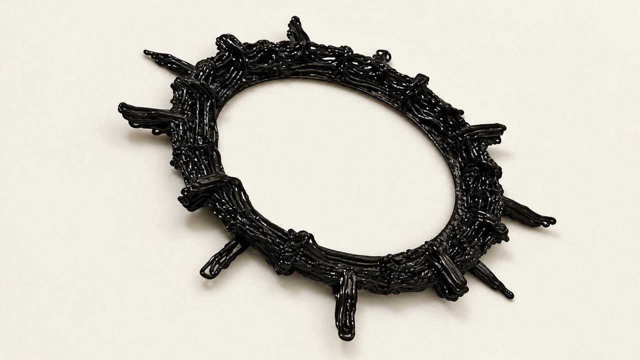
I'm returning to these experiments after a long break. I started by vibe-coding a new setup that takes print settings from a donor 3MF file, replaces its G-code with procedural code, and generates a web preview.
I didn't think I'd manage to print anything today, but here's what came out! The wall angle was too steep, so the filament didn't fuse properly. The little rays fused better.
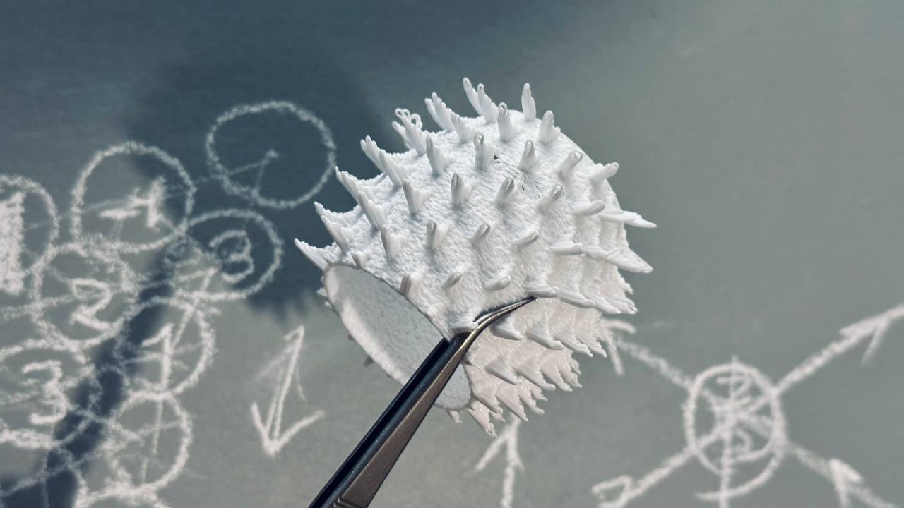
Geometric organics. I wanted to make something tactilely interesting, I think it worked out.
This is the third attempt: first had over-extrusion, second melted without a fan. Turns out I hadn't been using a fan before, and it worked fine. Midway through printing, the spool got stuck, but a miracle happened and it finished printing.
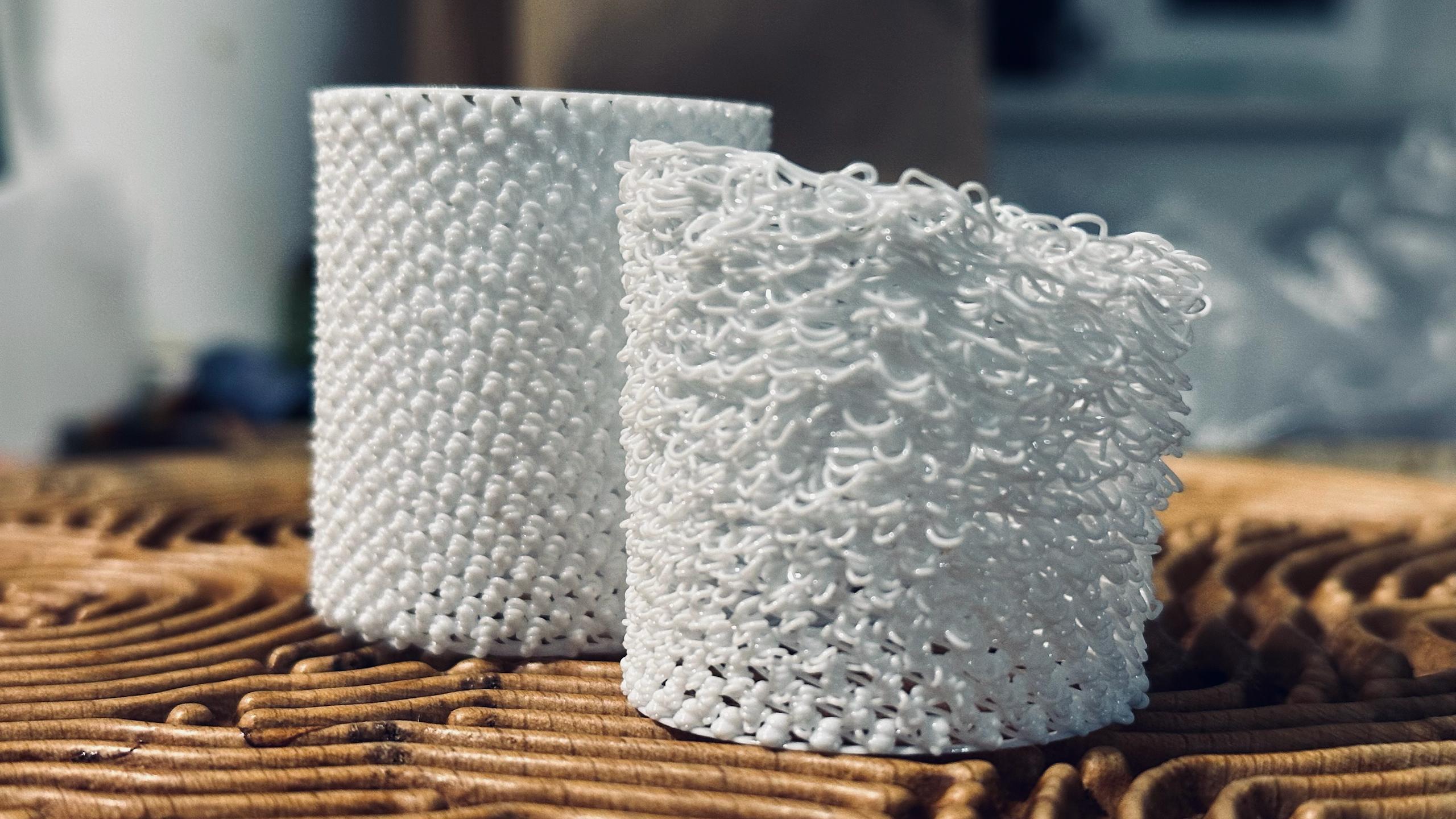
The transition to 3D turned out to be harder than I thought. First attempt was a disaster: the nozzle rose too fast and the wall couldn't keep up. But the second one stabilized — a sight to behold.
Decided to approach G-code generation systematically. Testing what happens with different heights and volumes of extruded plastic. Generated this trajectory with loops:
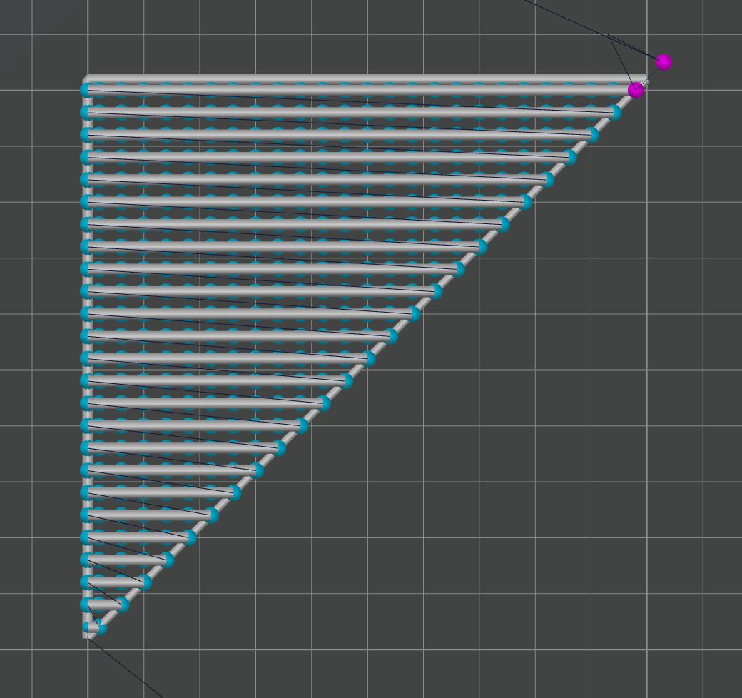
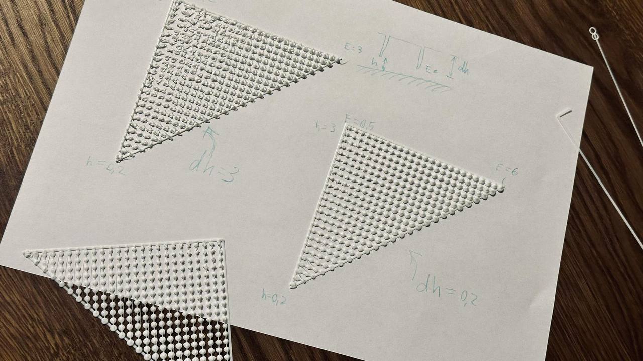
Got a matrix of bumps:
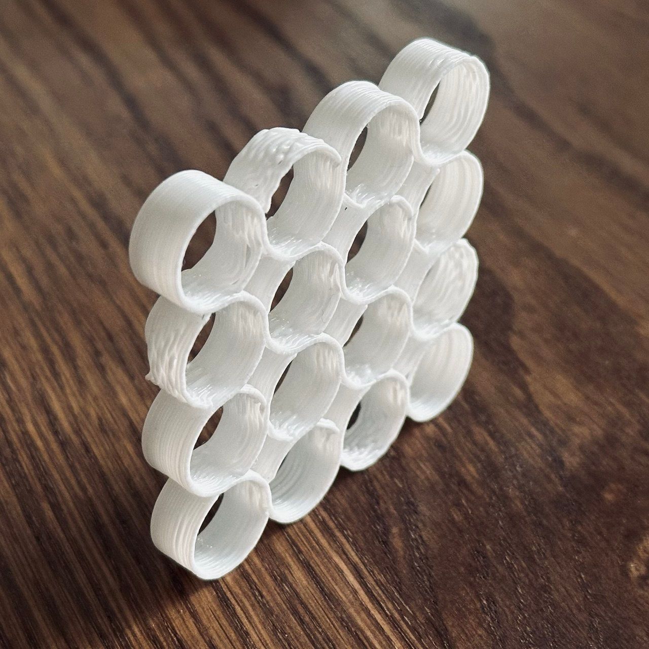
Another thing made with the same algorithm as yesterday's — a cellular automaton, but now packed into a hexagonal grid. Size is 4 cm.
The tubes fit tightly together, creating this honeycomb-not-honeycomb texture. I like how the print layers add organic feel — like some kind of coral.
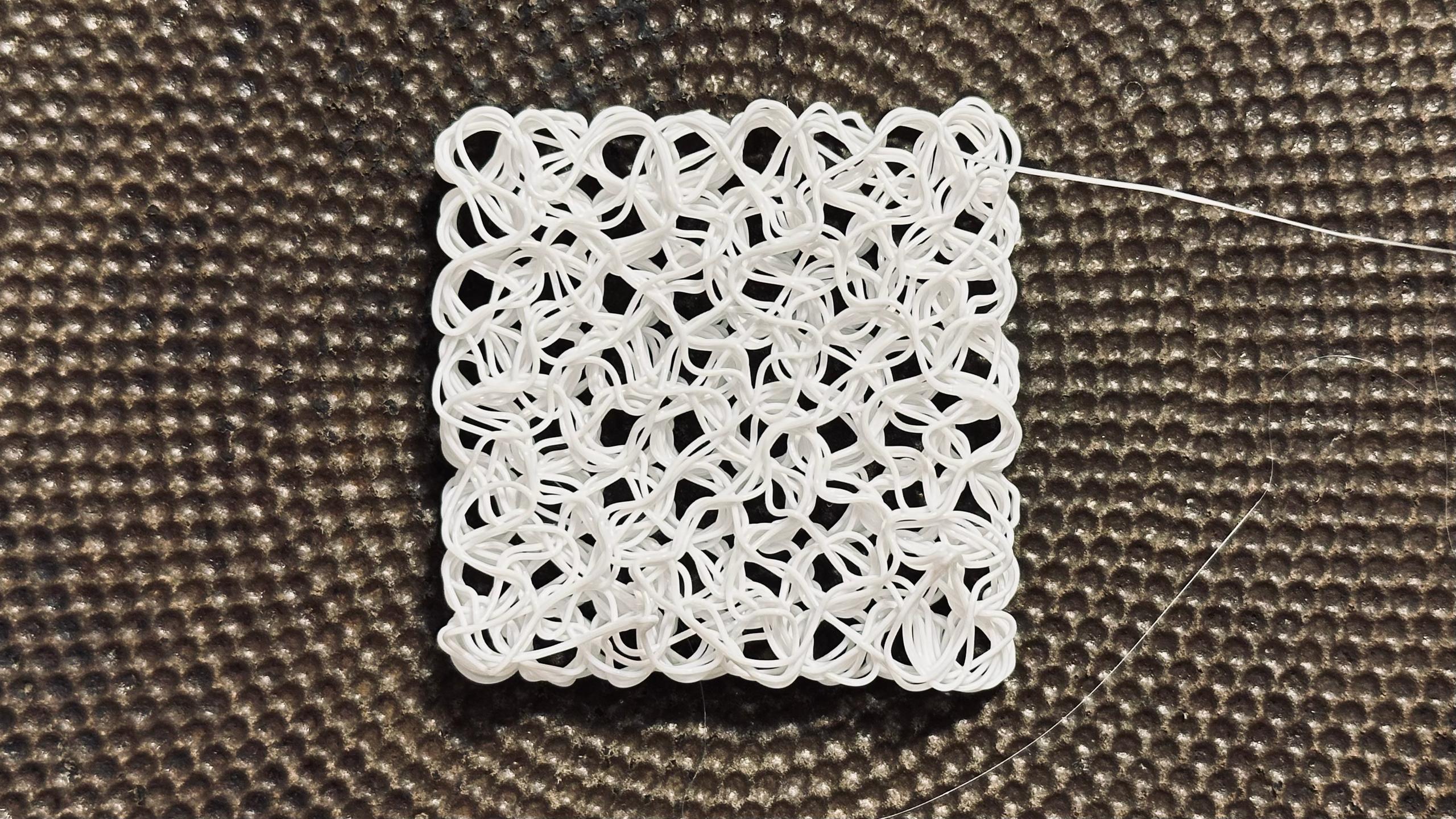
Put disproportionate effort into making this ramen noodle. First I ported yesterday's snake to G-code, then spent ages convincing the printer to extrude at least some plastic. Eventually it worked, I still don't understand why. Some non-obvious G-code magic. Or maybe I just haven't learned the ropes yet and the magic there is all obvious.
Learning to control a 3D printer through G-code. This is the language computers use to tell printers what to print — a long list of commands where to move and how much plastic to extrude.
Usually G-code is made by slicers: they take a 3D model, slice it into layers, and generate commands. But you can write G-code by hand! Then you can print not layer by layer, but up and down — creating lacy structures that a slicer couldn't handle.
Though if you mess up a digit, the printer will crash into the part at full speed and wreck everything with terrible sounds. Don't ask how I know this.
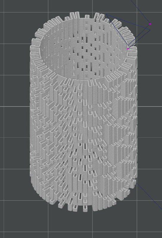
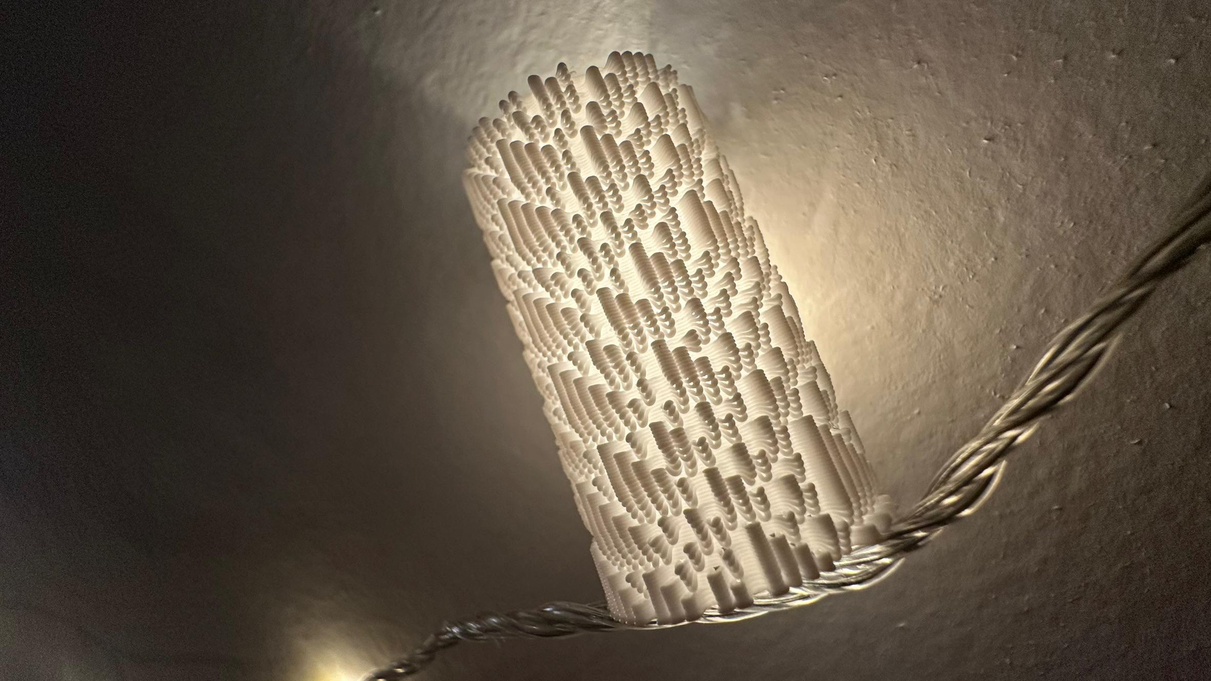
Tinkered for two days, got something cool. This is a one-dimensional cellular automaton — different steps are visible along the cylinder axis. I like the texture, like it's knitted.
In G-code viewer it looks like this
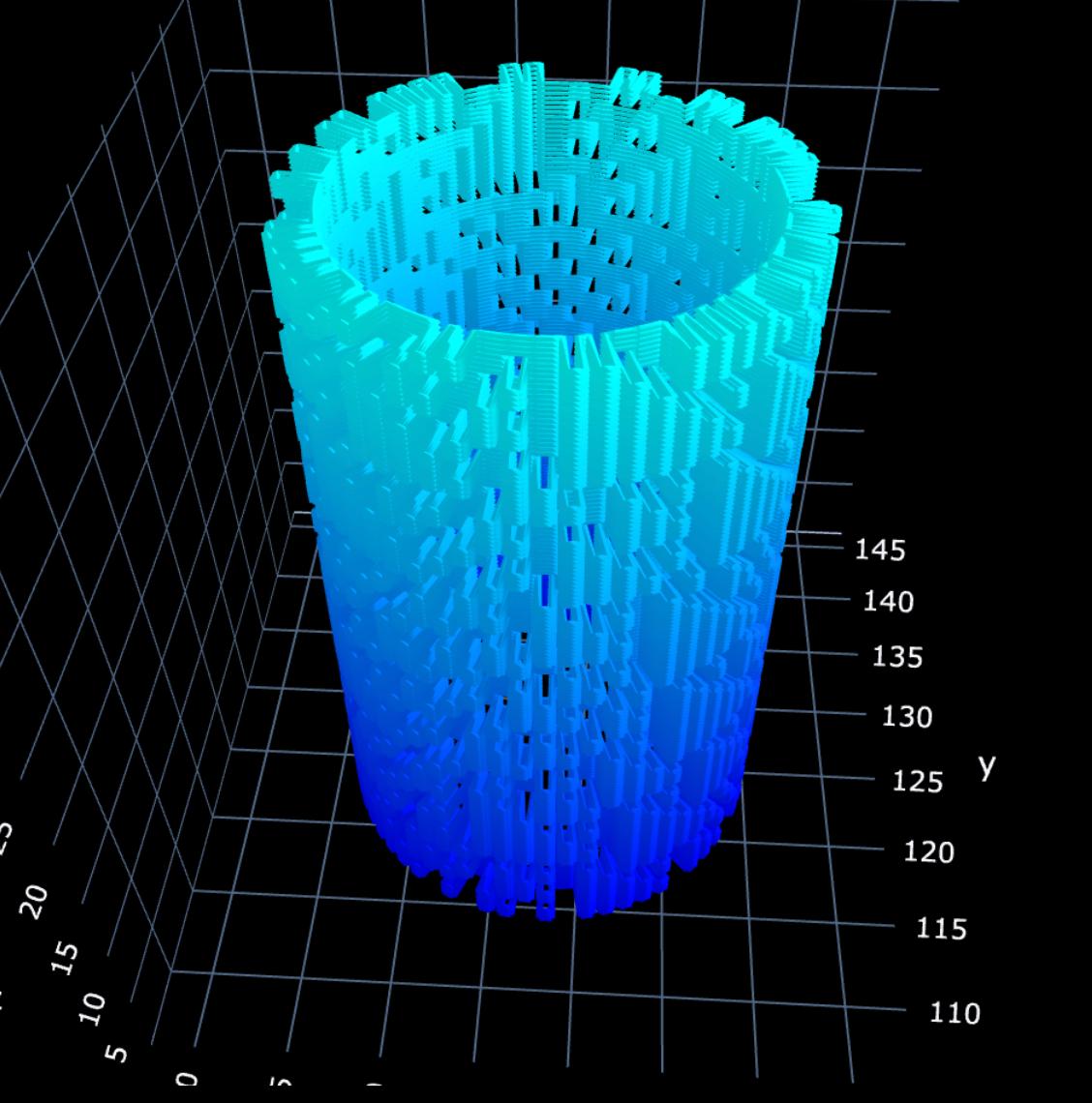
And in slicer like this