G-CODE → 2026-09-29
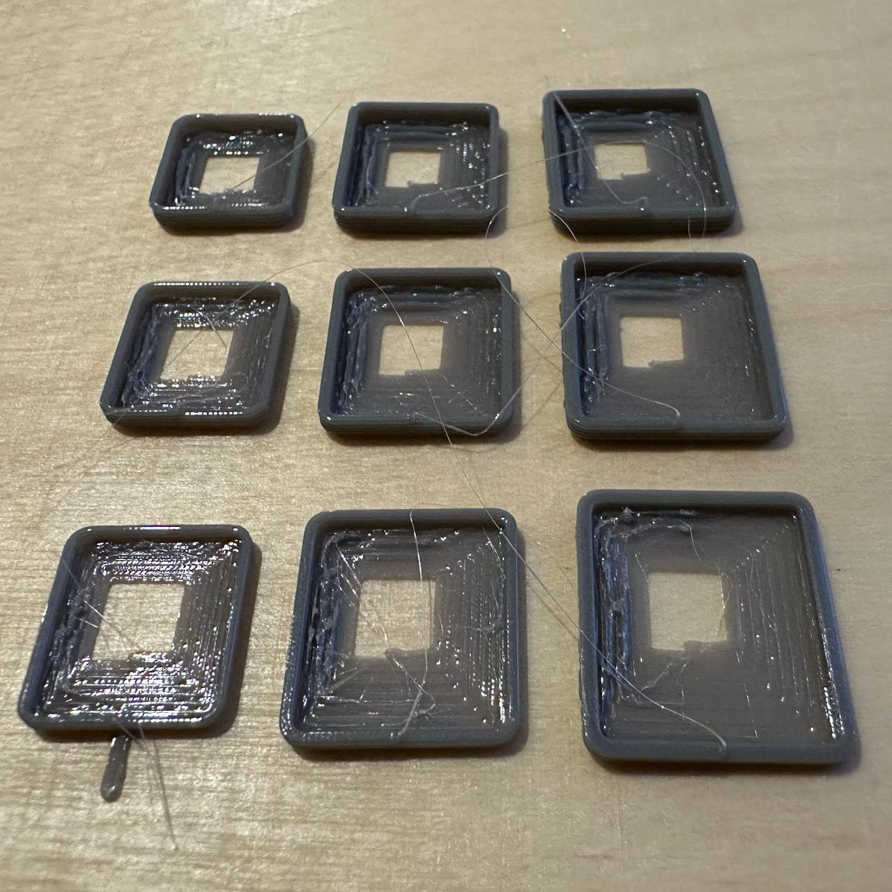
I want to print a Gridfinity box and am tuning the parameters. I varied line width along X, layer height along Y, and used a different floor-coil overlap on each of the four sides of every square. The floor was printed without cooling.
It came out strong even with the sparsest coils. The best result used the thickest layer, the widest line, and the least overlap: it is both fast and visually appealing.
I still need to work out how to close the central hole. I could place four drops in the centre and wind the spiral around them, or simply begin with one large drop.
Interestingly, 0% overlap is sufficient for almost every setting. Only the thinnest line also looks fine at 20%; for the other variants, that is already excessive.
Print parameters
Floor adhesion and initial rise probe — 2026-09-29 (sketch 2026.09.29 spiral floor probe, commit 998669c)
Ranges
| Axis | Variable | Values |
|---|---|---|
| X, left to right | line width | 0.6 / 0.8 / 1.0 mm |
| Y, front to back | layer height (floor and wall) | 0.3 / 0.4 / 0.5 mm |
| Side of the square (the same for all 9 samples) | floor-coil overlap | front 0%, right 20%, back 35%, left 50% |
The field corner is marked with a tail: on the front-left sample, a 5 mm extra segment protrudes from the edge where the floor transitions into the wall.
Print parameters
- Bambu Lab P1S, 0.4 mm nozzle, Textured PEI Plate
- Syntech PETG White, Ø1.75 mm, donor
_donor_3mf/L.gcode.3mf - Temperatures: nozzle 255 °C, bed 70 °C (donor temperatures)
- The sample uses the actual Gridfinity foot profile, size 2 (nominally 41.5 mm, without tolerance), from
2026.09.29 gridfinity foot probe: R0.8 rounding, then a 45° chamfer over 0.8 mm → 1.8 mm vertical section → 45° chamfer over 2.15 mm - Nine samples in a 3 × 3 grid, centres spaced 45 mm apart, field centred at X128 Y128
- Each sample is one continuous seamless spiral, printed at 20 mm/s throughout:
- Floor: from a 3 mm point to the edge (as in the foot), exactly 7 turns; cooling off. Each of the four sides has its own coil pitch and overlap (see ranges), so the final contour is a rectangle rather than a square: at a 1.0 mm line width, the distances from the centre to the edges are front 10.0 / right 8.6 / back 7.55 / left 6.5 mm.
- Wall: without stopping, the same spiral continues upward from the edge for another 5 turns along the actual foot profile (only the beginning of the rise, not the full 4.75 mm height); the side-to-side difference accumulated on the floor is preserved throughout the rise. Cooling is set to 100%.
- Corner rounding grows with the slowest side — the one with the least overlap
- The nozzle centreline is always offset inward from the true outer profile surface by half the line width
- Sample height ranges from 1.8 to 3.0 mm (6 turns at the row's layer height: 1 floor turn + 5 rising turns)
- Print time 4 min 36 s, filament 707 mm